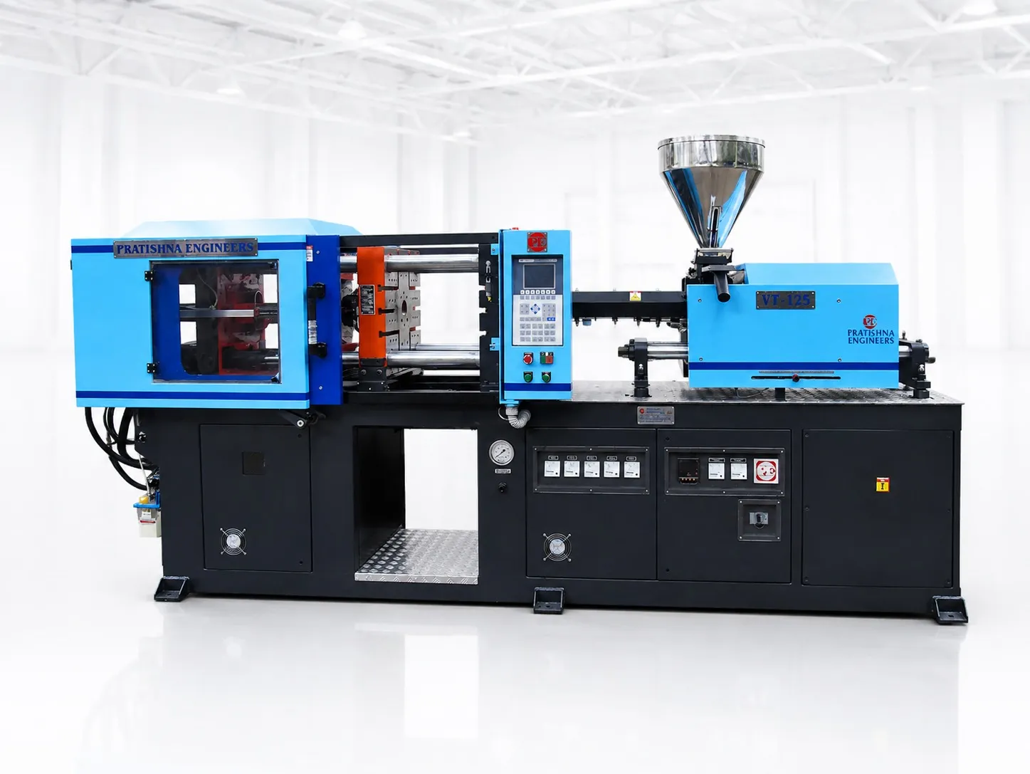
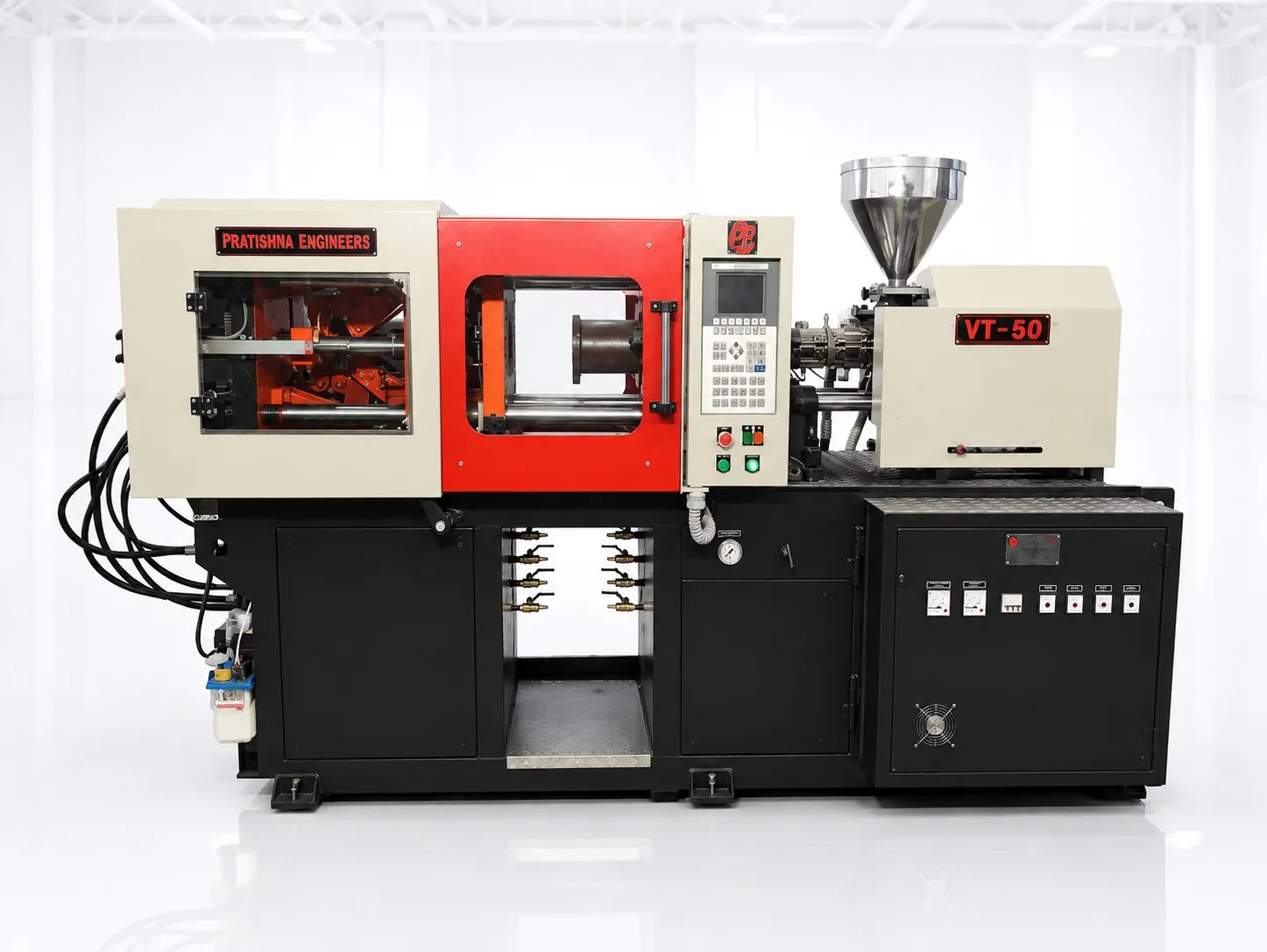
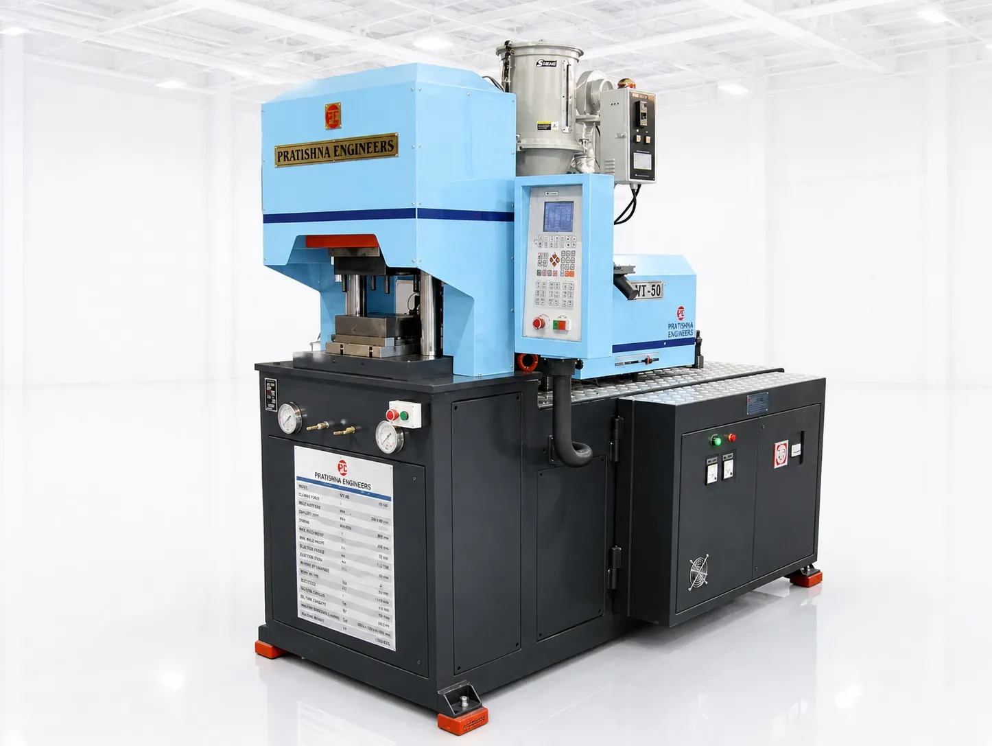
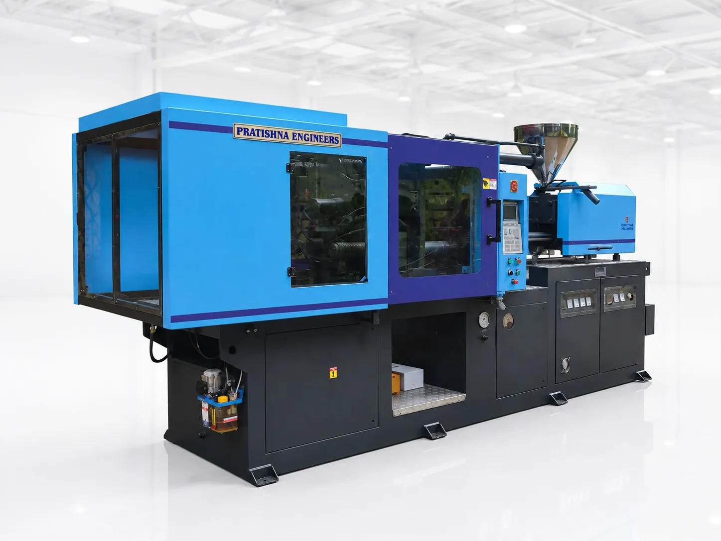
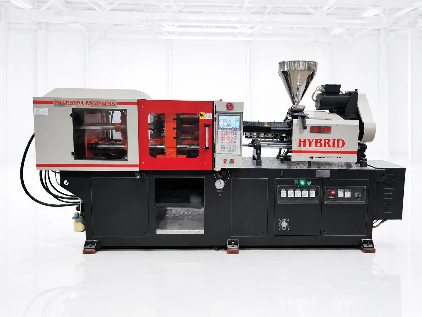

A setter closes a large crate mould on a two platen press and watches one cycle. The platen runs in fast, slows near the parting line, there is a short clunk as the nuts close on the tie bars, then the clamp pressure gauge climbs before the screw moves forward. That sequence is hydro-mechanical clamping. Small cylinders do the travel, mechanical locking nuts hold the position, and short-stroke hydraulic cylinders build the tonnage. Each part does one job, which is why the clamp can be set to the force a mould needs.
Key Takeaways
- Hydro-mechanical clamping splits the clamp into three jobs: fast travel, mechanical locking and short-stroke force build-up.
- Tonnage equals oil pressure times effective cylinder area, so it can be set and monitored for each mould.
- Short-stroke cylinders need only a few litres of oil to build tonnage, against far more for a full-stroke ram.
- Check locking time, mould height setting, mould protection and pump drive before you compare machines.
What happens in each stage of hydro-mechanical clamping?
A hydro-mechanical clamping cycle has five stages: fast close by traverse cylinders, slow approach with low pressure for mould protection, locking nuts closing on the tie-bar grooves, short-stroke cylinders building tonnage, then release and break-away before the traverse cylinders open the mould.
The five stages of a hydro-mechanical clamp cycle
| Stage | What moves | What to watch |
|---|---|---|
| 1. Fast close | Traverse cylinders move the moving platen at high speed | Speed profile and slow-down point |
| 2. Mould protection | Platen creeps in at low pressure until the halves touch | Protection pressure and time setting |
| 3. Lock | Split nuts close onto the tie-bar grooves | Locking time and engagement confirmation |
| 4. Clamp build-up | Short-stroke cylinders pressurise to the set tonnage | Set versus actual tonnage, build-up time |
| 5. Release and open | Pressure drops, cylinders break the mould open, nuts release, traverse opens | Break-away force for deep or sticky parts |
Stages 3 and 4 are where it differs from a toggle. Locking is mechanical, so once the nuts are closed the platen cannot be pushed back by injection pressure. Force then comes from oil acting on a large piston area over a few millimetres, which stretches the tie bars slightly and loads the parting line.
Plastics Technology describes the same principle in its review of hybrid clamps: split nuts or similar devices lock the moving platen, then one or more short-stroke "pancake" cylinders apply the tonnage.
How is clamp tonnage set and controlled?
Tonnage on a hydro-mechanical clamp equals oil pressure multiplied by the effective area of the clamp cylinders. Because area is fixed, the controller sets tonnage by setting pressure, and a pressure transducer can confirm it every cycle. You can run a mould at its calculated force rather than at maximum.
This matters more than it sounds. Over-clamping can burn parts, crush vents, roll the parting line, break inserts and crack mould blocks. Plastics Technology described a mould that needed about 100 tons being clamped at a 400-ton machine maximum; the cavity block split in two places, at a cost upwards of $100,000.
The same hybrid-clamp review reported that toggles can be hard to run below maximum tonnage or to ramp tonnage within a cycle, while direct hydraulic clamping is reported to give finer pressure control, more uniform pressure and better mould protection.
In practice, work out the clamp force each mould needs from its projected area, enter that figure, and record it on the mould setting sheet. If flash appears, look at process settings, vents and mould condition before you add tonnage. The specifications article in this series shows how to calculate the figure.
How is mould height set without a toggle adjustment?
In a typical hydro-mechanical clamp, mould height is set by where the locking nuts engage along the grooved tie bars. The traverse cylinders close the mould, the nuts lock at the nearest groove position, and the short-stroke cylinders take up the small remaining gap before building force.
Compare that with a toggle, where die height is adjusted mechanically. A reported drawback is that setting die height with the mould closed can over-clamp once the mould warms and expands. The trade-off on a two platen design is stroke: the mould and the opening share one daylight, so a taller mould leaves less opening.
Ask the supplier how often the grooves repeat along the tie bar and how the controller handles a mould whose height falls between two groove positions. The answer tells you how much of the short cylinder stroke is used up before any force is built.
Does hydro-mechanical clamping save energy?
It can, because the large cylinders hold tonnage over a very short stroke and need little oil volume, but the pump drive matters more. A fixed-speed pump running through holding and cooling wastes energy whatever the clamp design; a servo or variable pump cuts that waste.
An energy guide from ExxonMobil, AMI and Tangram Technology puts the base load of a standard hydraulic machine at 75% or more of its total energy, against about 10 to 20% for all-electric and hybrid machines. In Maharashtra, MSEDCL bills on kVAh, which MERC intended for HT consumers and LT consumers above 20 kW, so poor power factor costs you as well: at 0.85, 15% of the power drawn does no useful work.
My view: judge a hydro-mechanical clamp on locking time, tonnage repeatability and mould protection. The clamp layout alone will not cut your power bill; the pump drive and how you run the machine will.
What should you check on a hydro-mechanical clamp before buying?
Ask for the locking time, the tonnage range you can set, how mould height is found, the protection pressure, and measured power on a cycle like yours. Then compare machines on the same mould. See the two platen injection moulding machines.
Frequently Asked Questions About Hydro-Mechanical Clamping
Why are the clamp cylinders called pancake cylinders?
Because they are wide and very short. A large bore gives the area needed for tonnage, while a stroke of a few millimetres only has to stretch the tie bars and take up the small gap left after locking. Plastics Technology described them as short-stroke pancake cylinders in its review of hybrid clamps.
What happens if the locking nuts do not engage fully?
A partly engaged nut carries the clamp load on fewer groove faces, which can damage the nuts and tie bars. The machine should confirm engagement with sensors before it builds pressure. Ask how the interlock works and what the controller does if locking is not confirmed within the set time.
Why does the clamp need a break-away stroke?
After cooling, the mould halves can stick, especially on deep parts that grip the core. The short-stroke cylinders reverse to break the mould open before the nuts release, because the traverse cylinders are sized for speed rather than force. Ask for the break-away force if your parts are deep or have little draft.
Does mould protection work the same way on a two platen clamp?
The principle is the same: close the last part of the stroke at low pressure and stop if the mould meets resistance before the halves touch. On a hydro-mechanical clamp the traverse cylinders do this before locking, so a trapped part should stop the platen before any tonnage is built.
Do the tie bars need special care on a hydro-mechanical machine?
Yes. The grooved section and the locking nuts carry the full clamp load, so keep them clean and lubricated as the manual says, and check for wear or damage at each service. Watch for uneven tie-bar stretch as well, since unequal loading can affect platen parallelism and cause flash.
Related Articles
- What Is a Two Platen Injection Moulding Machine?
- Two Platen vs Toggle Injection Moulding Machines: Key Differences
- Important Specifications to Consider Before Buying a Two Platen Machine
- Applications of Two Platen Injection Moulding Machines
Sources & References
- Plastics Technology, M. Knights: Hybrid Injection Clamps: The Best of Both Worlds? (June 2010)
- Plastics Technology, J. Williams (RJG): Clamp Tonnage: More Is Better...Right? (May 2017)
- ExxonMobil, AMI and Tangram Technology: An Energy Saving Guide for Injection Moulders
- MSEDCL: kVAh Billing: Frequently Asked Questions
Technical Disclaimer
Disclaimer: The information provided in this document is for general informational and educational purposes only. It is based on technical references and industry information available at the time of preparation and may be subject to change. It does not constitute engineering, technical, commercial or professional advice, nor does it constitute a quotation, specification, warranty or contractual commitment by Pratishna Engineers.
Actual injection moulding machine and process requirements vary according to the component design, material, mould, production volume, machine configuration and operating conditions. The information, examples, calculations and recommendations provided should be independently evaluated and verified for the specific application before making any equipment, process or production decision. Information obtained from third-party sources remains subject to the accuracy and limitations of those sources.
Limitation of Liability: Pratishna Engineers makes no representation or warranty, express or implied, regarding the completeness, accuracy or suitability of the information for any particular application. To the extent permitted by applicable law, Pratishna Engineers shall not be liable for any loss, damage, cost or consequence arising from reliance on or use of the information contained in this document. Final machine selection, configuration and application suitability should be confirmed with Pratishna Engineers based on complete and accurate project requirements.