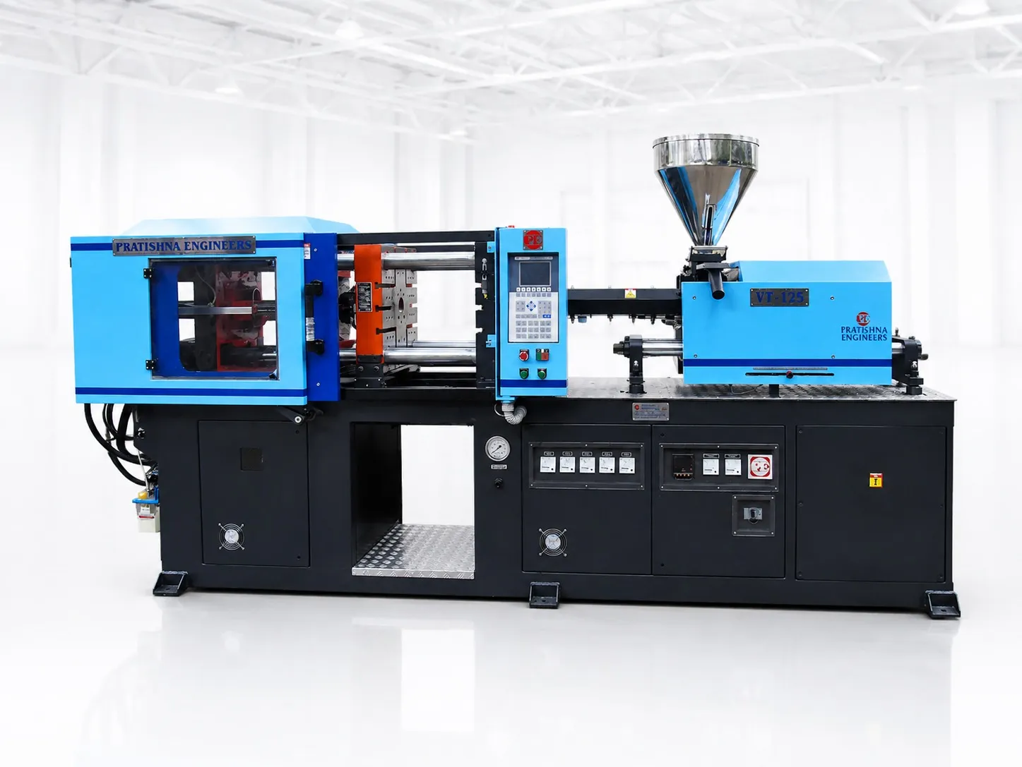
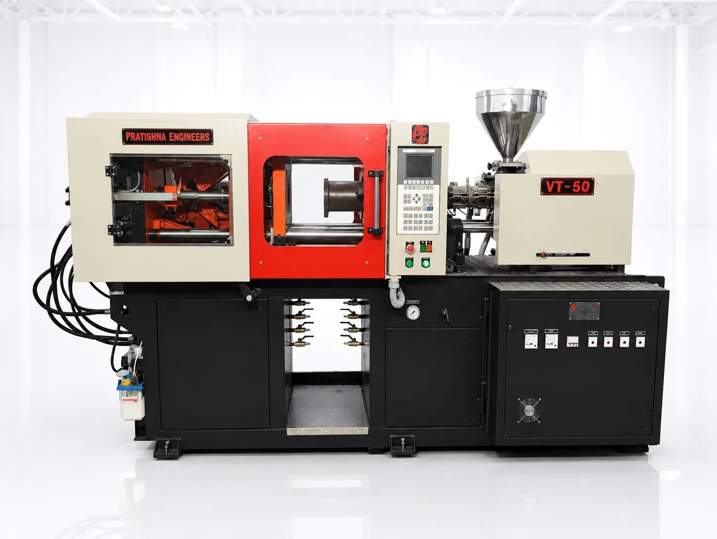
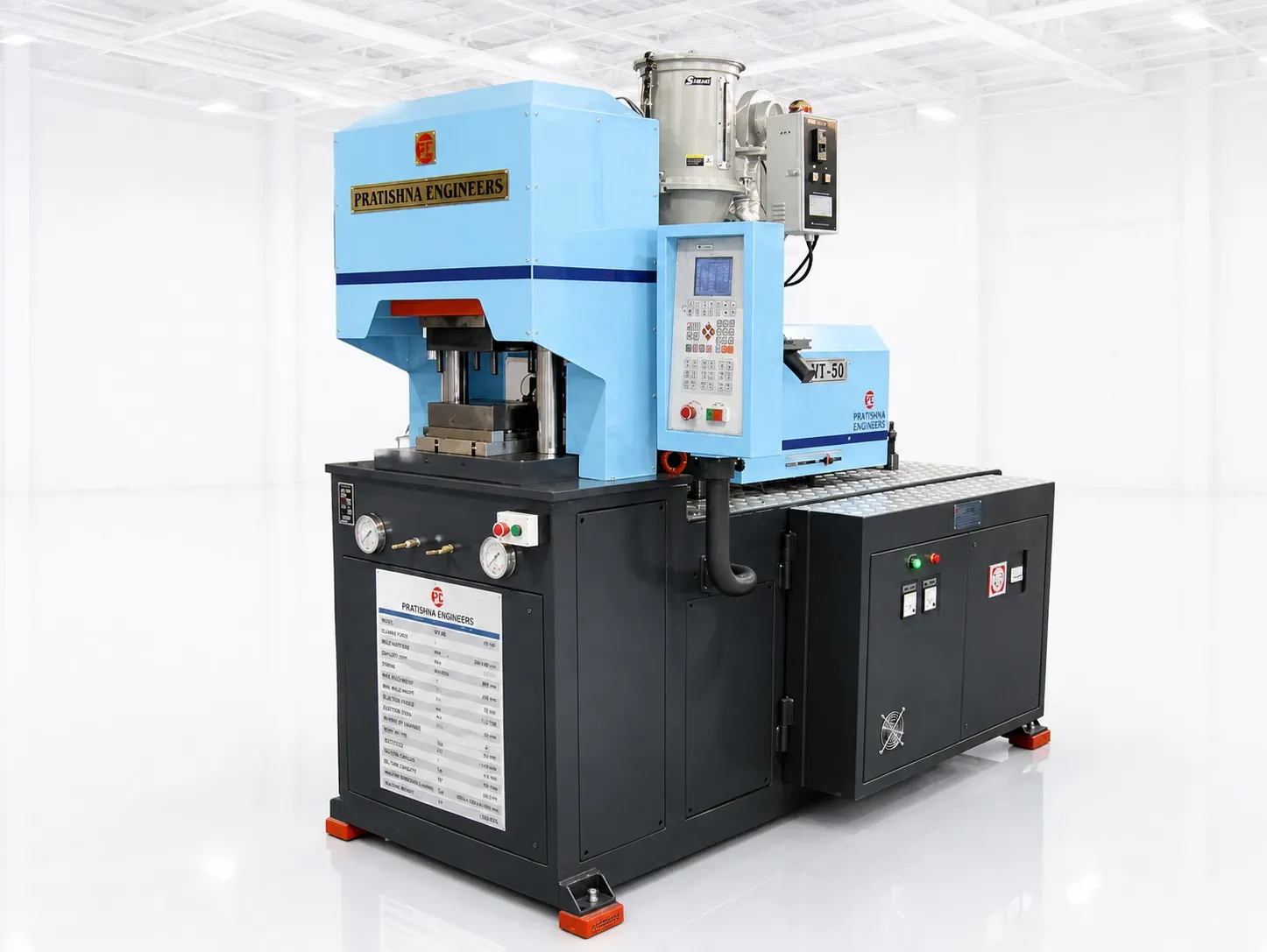
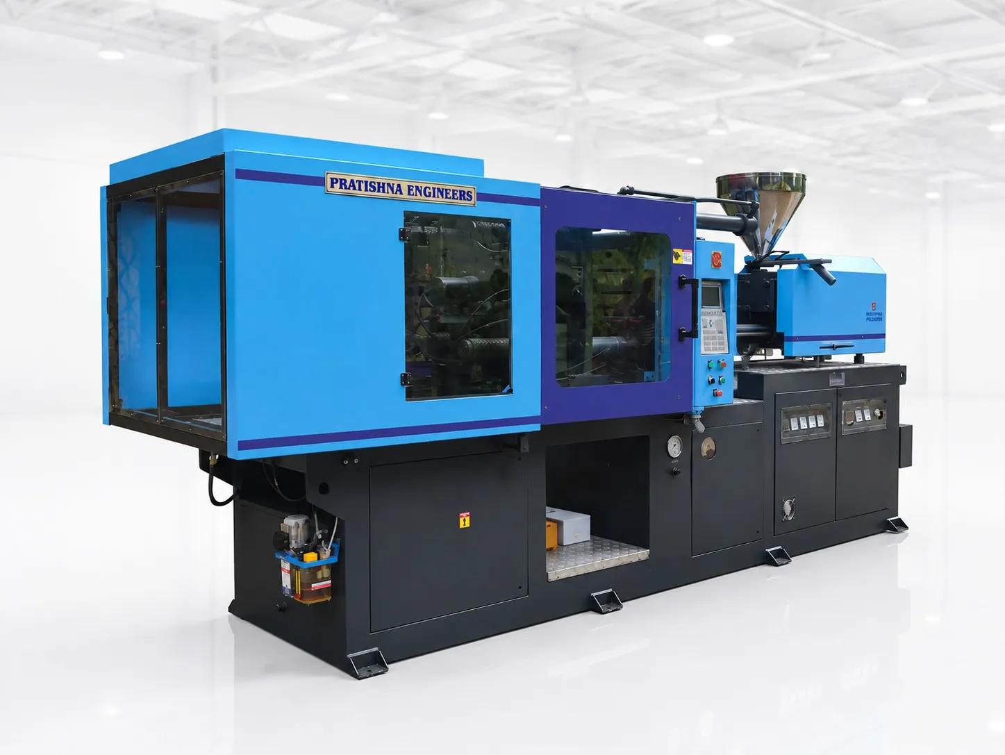
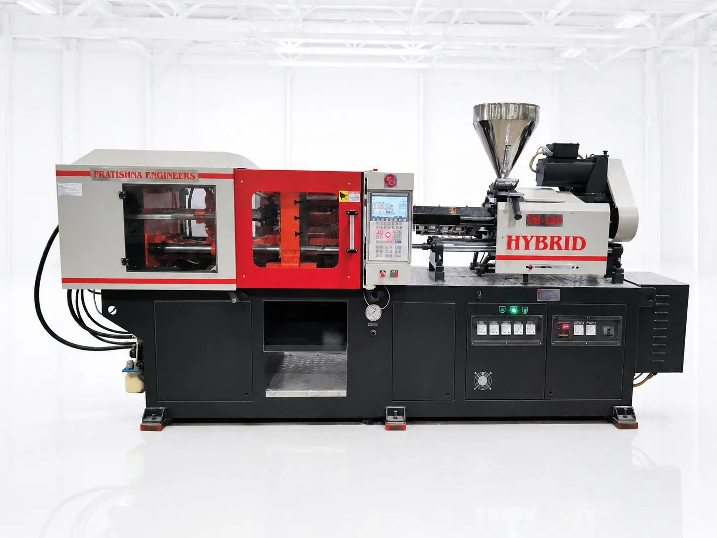
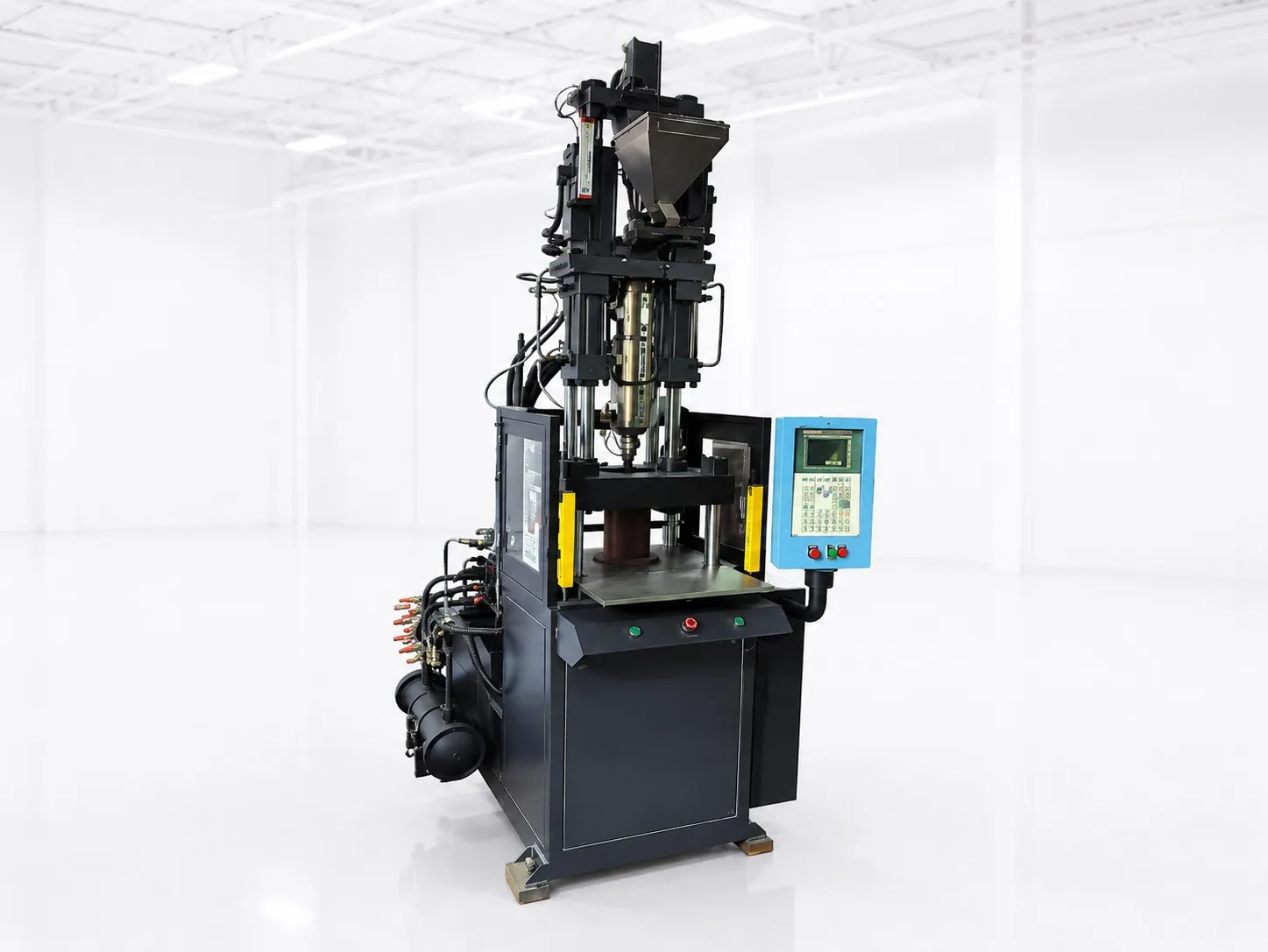
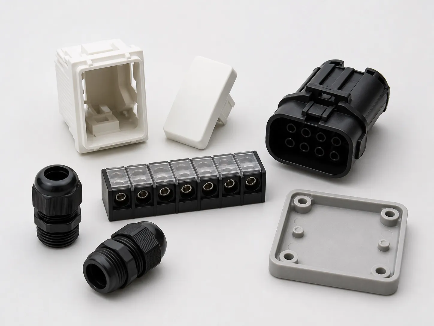

Take a two-cavity switch base of 30 cm² per cavity with a 6 cm² runner. At a tonnage factor of 3 to 5 US t/in² plus a 10% margin (a starting margin, not a rule), it needs about 31 to 51 t of clamp, so a 60 t clamp covers it with room to spare. Vertical machine specifications follow from numbers like these: clamp force, table type and size, opening, shot size, injection direction, working height and drive power, checked against your part and how you will load it.
Key Takeaways
- Clamp force comes from projected area times a tonnage factor, plus a margin; small insert parts may need little.
- Table type and table move time can decide output more than clamp force does.
- Size the barrel by volume so small insert shots do not fall below about 20% of capacity.
- Ask for measured power over a full cycle, including the time spent loading inserts.
Which vertical machine specifications matter most?
The vertical machine specifications that decide fit are clamp force, table type and size, the mould space between tie bars or frame, opening stroke, shot size, injection direction and the working height of the lower mould. Check them against your part, inserts and loading method before extra features.
Specifications to check on a vertical machine quote
| Specification | Why it matters | How to check |
|---|---|---|
| Clamp force (t) | Holds the mould shut against cavity pressure | Projected area × tonnage factor + margin |
| Table type and size | Sets stations, mould size and output | Number of lower halves, table move or index time |
| Tie-bar or frame opening (mm) | Mould fit and loading access | Mould plus clearance; access sides on C-frames |
| Opening stroke (mm) | Part and insert removal | Clears the part plus pins and gripper reach |
| Shot size (g PS) | The barrel must suit the shot volume | Shot at about 20% to 65% of barrel capacity |
| Injection direction | Gate position and cable routing | Through the mould or into the parting line |
| Working height (mm) | Operator comfort and robot reach | Lower mould height above the floor |
| Drive and power (kW) | Running cost while loading | Measured kW over a full cycle |
How do you size clamp force for small insert parts?
Multiply the projected area of the cavities plus any cold runner by a tonnage factor, then add a reserve. Plastics Technology suggests 3 US tons/in² as a starting factor, with typical factors from 2 to 10 depending on flow length, wall thickness, gating and material.
In metric, 3 US t/in² is 0.422 t/cm² and 5 is 0.703 t/cm². Through holes cored out by pins are subtracted from the area, while a metal insert lying flat at the parting line does not reduce it, since melt pressure acts all around it.
For small insert parts, tonnage can be less of a limit than table size and the number of cavities an operator can load in the time. Do not buy far more clamp than the job needs; the same Plastics Technology article lists burns, crushed vents, rolled parting lines, broken inserts and cracked blocks among the effects of over-clamping.
Multi-cavity insert tools change the picture. Clamp may still be small, but the platen or table has to be large enough for all the cavities plus the runner and the space the operator needs to reach each pin. Sometimes the table size, not tonnage, pushes you to the next machine.
How do you check the table, opening and working height?
Check that each lower mould half fits the table with clearance, that the table moves or indexes fast enough for your cycle, that the opening clears the part plus any pins and gripper, and that the lower mould sits at a height the operator can load all shift.
Table move time sits inside every cycle on a shuttle machine, so ask for it with your mould weight on the table, and ask for the maximum mould weight the table carries. Ask also whether table motion is interlocked with the loading zone.
For rotary tables, ask for the index time and the position repeatability at each station. A table that stops a little off position can knock inserts off their pins or mark the parting line, and the error shows up as scattered rejects rather than a clear fault.
ISO 20430:2020 sets safety requirements for the design and construction of injection moulding machines with hydraulic or electric platen drives. It does not apply to machines built before it was published, so ask the supplier whether the machine on your quote is designed to it, and how the loading station is guarded.
How do you match shot size and running cost?
Work in volume: convert the shot to cm³ using melt density, add 10% for check-valve leakage and melt uniformity, then pick a barrel where the shot sits at no more than 65% of capacity. Small insert shots can fall below about 20%, which risks long residence and degradation.
Shot ratings are usually given in grams of PS, so convert: PS melt density is 0.945 g/cm³ and PP about 0.74. Running cost depends on what the pump does while the operator loads inserts. In Maharashtra, MSEDCL charges demand on kVA and energy on kVAh, so a pump motor idling at poor power factor costs you on both counts; at 0.85, 15% of the power drawn does no useful work. Capacitors or an APFC panel help, and a servo pump cuts the idle draw itself.
Injection direction belongs on this list too. Decide it with the mould maker before you order, because it sets where the gate sits and how cables or long inserts leave the mould.
My view: on a vertical machine, idle kW during loading matters more than peak kW, so ask for power measured over a full cycle with your loading time in it.
What should you send to get a correct specification?
Send the part and insert drawings, the material grade, cavities, shot weight, lower and upper mould sizes and weights, loading method and target output. A supplier can then fill the table above for your job. See the vertical injection moulding machine range.
Frequently Asked Questions About Vertical Machine Specifications
What table size do I need on a vertical machine?
Size the table from the largest lower mould half plus clearance for clamping and loading, then confirm the maximum mould weight covers it. On a shuttle machine both lower halves travel, so check the table carries their combined weight at the stated move time without overshoot.
Does injection direction affect the mould design?
Yes. Vertical injection gates through the top or centre of the mould, while horizontal injection enters at the parting line, which suits cables or long inserts lying across it. The choice sets gate position, runner layout and where inserts can sit, so decide it with the mould maker before ordering.
Is a bigger shot capacity always safer?
No. A shot below about 20% of barrel capacity stays in the barrel for many cycles and can degrade, and above 65% melt quality can suffer. Plastics Technology columnist John Bozzelli advises against buying the biggest screw; size the barrel to your typical shot and add a second barrel if the range is wide.
What safety features should a vertical machine have?
Guarding that matches how inserts are loaded: interlocked gates or light curtains at the loading station, table motion that stops when the zone is entered, and two-hand controls where the operator works near closing parts. Ask whether the design follows ISO 20430:2020, the safety standard for injection moulding machines.
Should the working height of the lower mould matter?
Yes, because operators load inserts there all shift. The height is set by the machine base and mould, so check it with your operators before you buy. A platform or lower base can correct it, but changing it later costs time. Test it with the people who will load during the machine trial.
Related Articles
- What Is a Vertical Injection Moulding Machine?
- How Does Insert Moulding Work on a Vertical Machine?
- Horizontal vs Vertical Injection Moulding Machines: Key Differences
- Applications of Vertical Injection Moulding Machines
Sources & References
- Plastics Technology, J. Williams (RJG): Clamp Tonnage: More Is Better...Right? (May 2017)
- Plastics Technology, J. Bozzelli: A Simpler Way to Calculate Shot Size vs. Barrel Capacity (2017, updated 2022)
- ISO: ISO 20430:2020 Plastics and rubber machines: Injection moulding machines: Safety requirements
- MSEDCL: kVAh Billing: Frequently Asked Questions
Technical Disclaimer
Disclaimer: The information provided in this document is for general informational and educational purposes only. It is based on technical references and industry information available at the time of preparation and may be subject to change. It does not constitute engineering, technical, commercial or professional advice, nor does it constitute a quotation, specification, warranty or contractual commitment by Pratishna Engineers.
Actual injection moulding machine and process requirements vary according to the component design, material, mould, production volume, machine configuration and operating conditions. The information, examples, calculations and recommendations provided should be independently evaluated and verified for the specific application before making any equipment, process or production decision. Information obtained from third-party sources remains subject to the accuracy and limitations of those sources.
Limitation of Liability: Pratishna Engineers makes no representation or warranty, express or implied, regarding the completeness, accuracy or suitability of the information for any particular application. To the extent permitted by applicable law, Pratishna Engineers shall not be liable for any loss, damage, cost or consequence arising from reliance on or use of the information contained in this document. Final machine selection, configuration and application suitability should be confirmed with Pratishna Engineers based on complete and accurate project requirements.