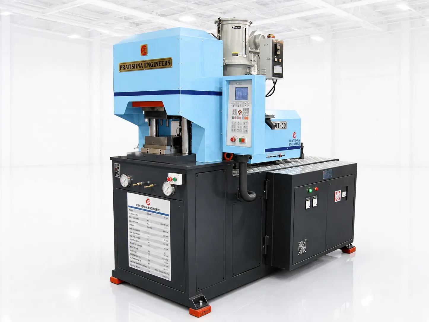
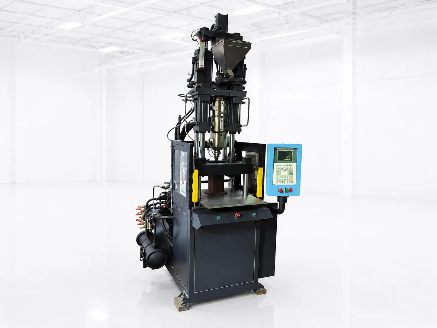

An operator at a vertical machine picks four brass bushes from a tray, drops each onto a core pin in the lower mould half, presses two buttons and steps back. The table slides the loaded half under the top mould, the clamp closes and plastic flows around the bushes. Meanwhile the other half slides out with four finished parts. That is the insert moulding process on a vertical machine: load, check, close, inject, cool, open and unload, with a shuttle or rotary table letting loading overlap moulding.
Key Takeaways
- The insert moulding process adds two steps to every cycle: placing inserts and checking they are seated.
- A shuttle or rotary table lets loading happen while the other mould half is being moulded.
- Inserts must locate on close-fitting pins; loose inserts float, flash or damage the mould.
- With a table, cycle time becomes the longer of moulding and loading, plus table movement.
What are the steps in the insert moulding process?
The insert moulding process runs in six steps: place inserts on locating pins in the lower half, check they are seated, close the clamp, inject and pack around them, cool, then open and remove the part. On a table machine, loading and removal happen at a station outside the clamp.
The six steps and what goes wrong at each
| Step | What happens | What goes wrong if rushed |
|---|---|---|
| 1. Load | Insert placed on a pin or in a pocket | Missing insert, wrong orientation |
| 2. Verify | Operator, sensor or vision confirms seating | Crushed insert, damaged mould |
| 3. Close | Top half comes down and the mould locks | Insert knocked off its pin |
| 4. Inject and pack | Melt flows around the insert | Flash into threads, weak weld lines |
| 5. Cool | Plastic freezes and shrinks onto the insert | Locked-in stress, cracks later |
| 6. Open and unload | Part lifted out, pins cleared | Debris left for the next load |
Steps 1 and 2 are where insert jobs win or lose. In an RIA case study of an automated cell, it took 30 s to unload a four-cavity mould, inspect the cavities for debris, and load and verify the inserts. The cell used a SCARA robot, fed inserts from a vibratory bowl feeder, and used vision to confirm cavities were clear and inserts seated before moulding. A post-mould vision check kept bad parts in the cell, and consistent mould-open times removed mould temperature swings.
How do shuttle and rotary tables change the cycle?
With a fixed table the clamp waits while you load. With a shuttle or rotary table, one lower half is loaded while the other is moulded, so the cycle becomes the longer of moulding time and loading time, plus the time the table takes to move.
A PlasticsToday report describes the conventional shuttle layout: one top A half and two bottom B halves, with the operator loading one B half while the press moulds the other. It also notes the catch: the machine must wait for the first part to cool in the clamp before it moulds the second, so cooling stays inside the cycle.
A single-slide table, with one lower half that slides out for loading, saves reach and improves safety but adds two table moves to every cycle. The worked example below shows what a double slide gains and what a single slide costs.
A rotary table goes further. With three or four stations, one can be for loading, one for moulding and one for unloading or inspection, so a second operator or a robot can work without waiting. The more stations, the more lower mould halves you pay for, so match stations to the real steps in your cycle.
How should inserts be designed and held?
Inserts should have rounded knurling and no sharp corners, an undercut or groove to resist pull-out, and a close fit on their locating pin. DuPont guidance also has them protrude at least 0.4 mm into the cavity, with at least one-sixth of the insert diameter of plastic beneath.
Preheating the insert helps: the same guidance says it reduces post-mould shrinkage around the metal, pre-expands the insert and improves weld lines. Delayed cracking from hoop stress is the complaint that comes up most with moulded-in metal; the applications article in this series works through the numbers for nylon.
Fit matters more than people expect. An insert that can lift will float in the melt, and one that sits proud will be crushed when the mould closes. Keep pin and insert tolerances on the drawing and check incoming inserts against them. Supplied inserts with burrs, oil or plating build-up can cause poor seating, so add those checks to your incoming inspection.
How do Indian rules affect insert-moulded electrical parts?
Several electrical accessories that carry metal parts now need the BIS Standard Mark. The Electrical Accessories (Quality Control) Order, 2023 made it compulsory for products including boxes and enclosures to IS 14772, bayonet lamp holders to IS 1258 and switch-socket-outlets to IS 15787.
The order, S.O. 43(E) dated 1 January 2024, came into force six months after publication, nine months for small and twelve for micro enterprises, and excludes goods made for export. For a moulder, that means the finished part has to pass the standard, so insert retention and moulded-in stress become quality points, not just production ones.
My view: if a part must pass a certification test, automate insert verification before you automate loading.
What should you send for an insert moulding enquiry?
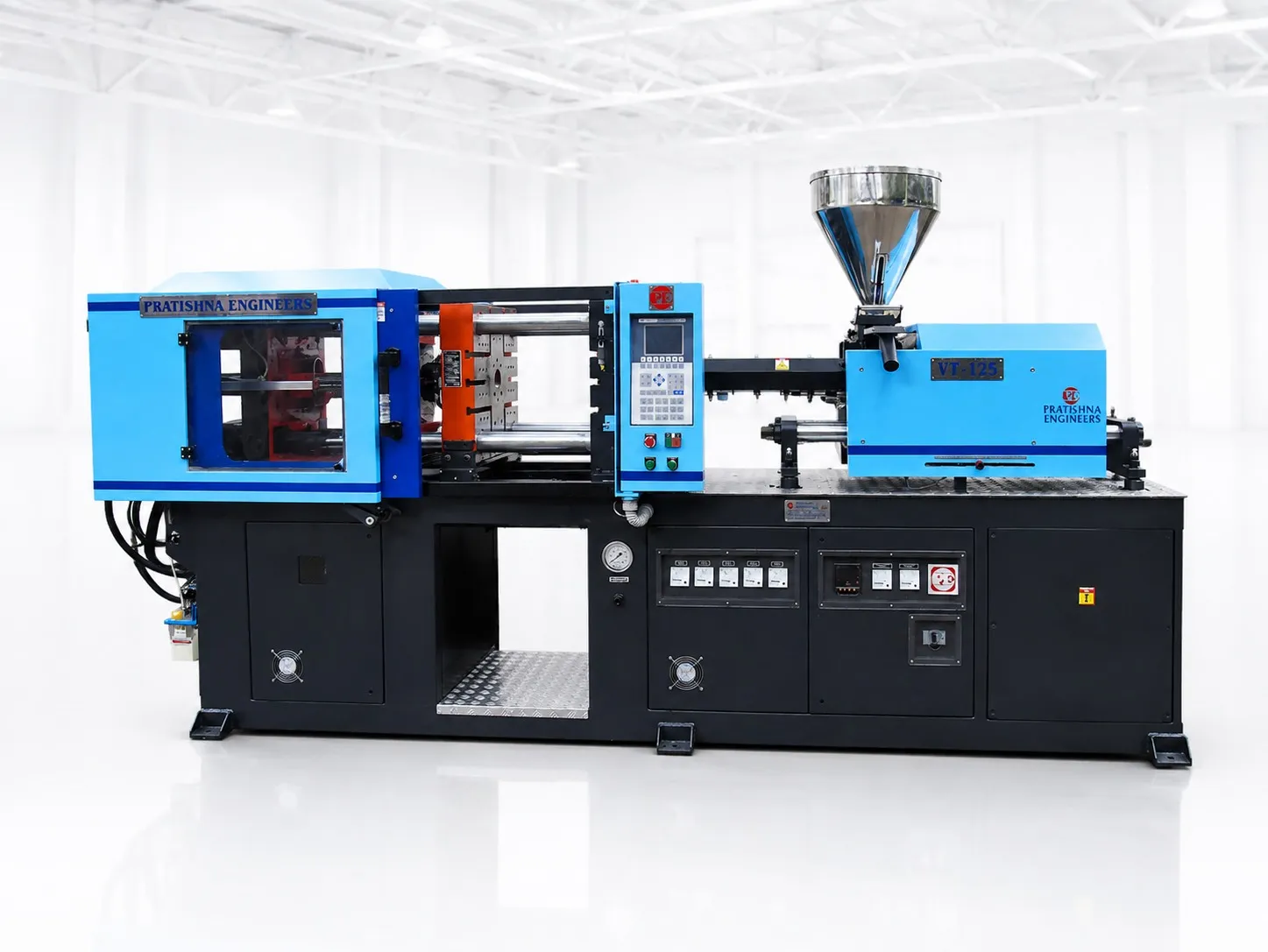
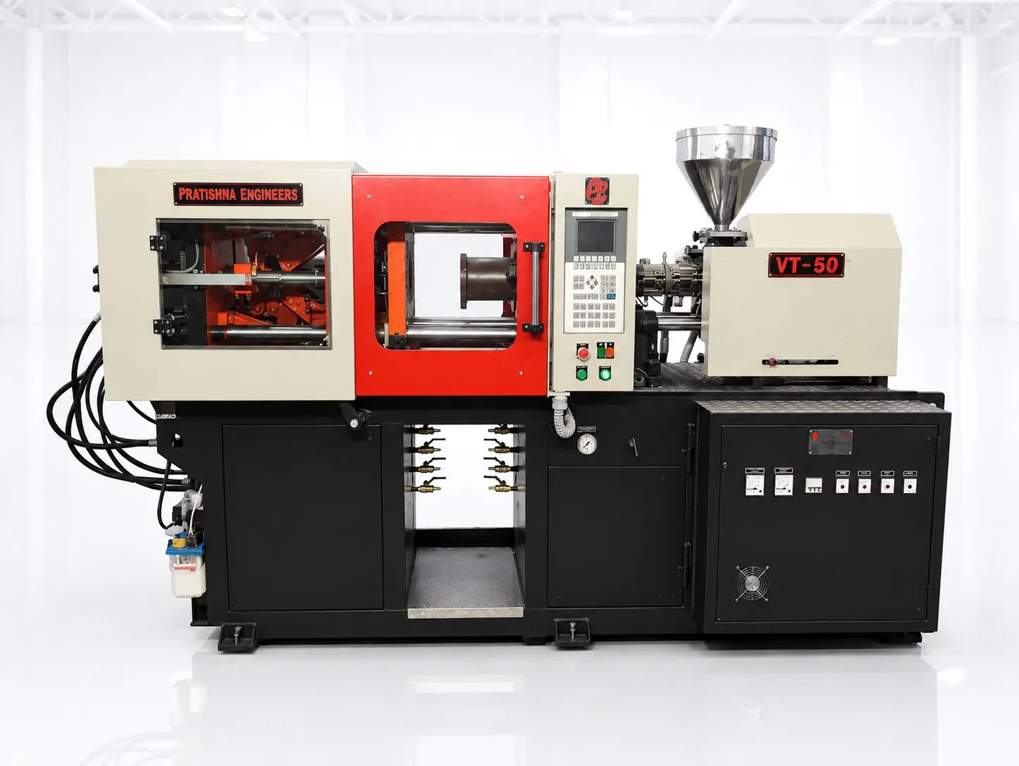
Send the part and insert drawings, the insert material and supply form (loose, on reel or in trays), inserts per shot, cavities, the plastic grade and your target output. That is enough to compare fixed, shuttle and rotary layouts. See the vertical injection moulding machine range.
Frequently Asked Questions About Insert Moulding
Can inserts be pressed in after moulding instead?
Often, yes. DuPont guidance summarised by PlasticsToday notes that inserts can often be pressed, snap-fitted or ultrasonically inserted into a moulded part, and treats moulding in as a last resort. Mould in when you need serviceable threads under stress, close-tolerance female threads or a permanent joint between high-load parts.
How do you stop flash getting into insert threads?
Seat the insert firmly so the mould shuts off against it, keep injection and pack pressure no higher than the part needs, and hold pin and insert tolerances. Blind or plugged threads are easier to keep clean than open through-threads. Check the first parts of every shift for flash inside the thread.
How many inserts can an operator load per cycle?
It depends on placement time. At an assumed 2 s per insert plus 6 s to remove and check the part, ten inserts take 26 s; at 1.5 s each, 21 s. On a fixed table that time adds to every cycle, which is why high insert counts push towards shuttle tables or robots.
What does vision inspection check in an insert cell?
In the RIA case study, vision checked before each shot that cavities were free of debris and inserts were seated, and a post-mould check kept bad parts in the cell. Pre-mould checks protect the mould; post-mould checks protect your customer. Start with pre-mould checks if you can afford only one.
Is a rotary table better than a shuttle table?
A rotary table can hold two or more lower halves and add stations for loading, inspection or unloading, while a shuttle has two halves sliding side to side. Rotary suits longer runs with several manual or robotic steps; shuttles are simpler and need less space. Compare both on cycle and floor plan.
Related Articles
- What Is a Vertical Injection Moulding Machine?
- Horizontal vs Vertical Injection Moulding Machines: Key Differences
- Important Specifications to Consider Before Buying a Vertical Machine
- Applications of Vertical Injection Moulding Machines
Sources & References
- PlasticsToday (IMM), summarising A. Miller, DuPont: Design and material advice from the pros, Part 3: Insert molding essentials (Sept 2005)
- PlasticsToday: Shuttle table increases production (Aug 2008)
- Robotic Industries Association via Smart Molding, J. Clark: Automated injection molding operation
- Gazette of India (DPIIT): Electrical Accessories (Quality Control) Order, 2023
Technical Disclaimer
Disclaimer: The information provided in this document is for general informational and educational purposes only. It is based on technical references and industry information available at the time of preparation and may be subject to change. It does not constitute engineering, technical, commercial or professional advice, nor does it constitute a quotation, specification, warranty or contractual commitment by Pratishna Engineers.
Actual injection moulding machine and process requirements vary according to the component design, material, mould, production volume, machine configuration and operating conditions. The information, examples, calculations and recommendations provided should be independently evaluated and verified for the specific application before making any equipment, process or production decision. Information obtained from third-party sources remains subject to the accuracy and limitations of those sources.
Limitation of Liability: Pratishna Engineers makes no representation or warranty, express or implied, regarding the completeness, accuracy or suitability of the information for any particular application. To the extent permitted by applicable law, Pratishna Engineers shall not be liable for any loss, damage, cost or consequence arising from reliance on or use of the information contained in this document. Final machine selection, configuration and application suitability should be confirmed with Pratishna Engineers based on complete and accurate project requirements.