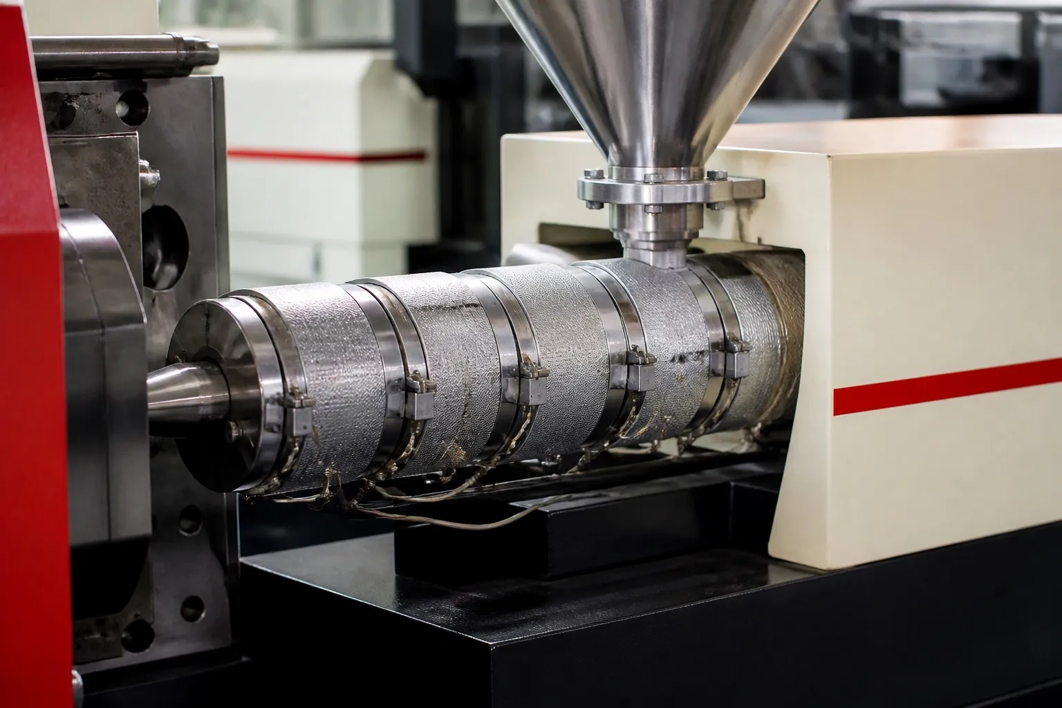

It is the second shift, and the setter on a four-cavity connector mould is nudging the transfer position again. Part weight has crept since morning as the oil warmed, and the far cavity is close to short. On a ball screw injection unit, that drift has fewer places to come from. A servo motor turns a ball screw, the screw position is counted from the motor encoder, and injection pressure is read by a load cell behind the screw. Speed, position and pressure follow the set profile with no oil in the injection path.
Key Takeaways
- A servo motor drives a ball screw, often through a belt, and the ball nut pushes the injection screw forward.
- Position comes from the motor encoder and pressure from a load cell at the back of the screw, so both are measured close to the melt.
- Ball screws turn rotation into thrust at typically more than 90% efficiency, and a preloaded nut removes backlash.
- The drive is only as repeatable as the melt behind it; a worn check ring will defeat any servo.
How does a ball screw injection unit move the screw?
The servo motor turns a pulley or gearbox, which turns the ball screw shaft. The ball nut is fixed to the plate that carries the injection screw and cannot rotate, so it travels along the shaft and pushes the screw forward. Reversing the motor pulls it back for decompression.
Inside the nut, steel balls roll in matching grooves on the shaft and nut and recirculate through a return path. Thomson, a linear motion component maker, gives ball screw efficiency as typically above 90%, because the balls roll instead of sliding. Preloading the nut removes free play between nut and shaft, which improves repeatability and stiffness but adds some turning torque.
Screw rotation for melting is handled by a separate drive, electric or hydraulic. During recovery the injection motor controls back pressure by resisting the screw as melt pushes it backwards, using the load cell reading to decide how hard to resist.
Hydraulic injection vs servo ball screw injection
| Item | Hydraulic injection | Servo ball screw injection |
|---|---|---|
| Force source | Oil pressure on a ram | Motor torque through the ball screw |
| Screw position | Linear transducer on the ram | Motor encoder counts, converted by the screw lead |
| Pressure reading | Oil pressure times the intensification ratio | Load cell behind the screw, read as plastic pressure |
| Main drift sources | Oil temperature, valve response, leakage | Check ring wear, load cell zero, ball screw wear |
| Routine care | Oil, filters, seals | Ball screw lubrication, encoder and load cell checks |
Why does electric injection repeat shot weight more closely?
Because it drives and measures the screw directly. Position is counted from motor revolutions and the screw lead, and pressure is read at the screw instead of being worked out from oil pressure. No oil compression, temperature change or valve lag sits between the controller and the melt.
On a hydraulic unit, the controller sees oil pressure, and plastic pressure is that figure times the intensification ratio, the ram area divided by the screw area. J. Bozzelli, writing in Plastics Technology, notes ratios from 6:1 to 43:1 across machines, changing with screw size, and that electric machines read plastic pressure directly. At 10:1, a 1 bar error on the oil side is a 10 bar error at the melt.
A PlasticsToday report on sensors found that most makers of electric machines measure injection pressure with a load cell at the back of the screw, and quoted a sensor specialist saying this is more accurate than hydraulic sensing because it sits closer to the process.
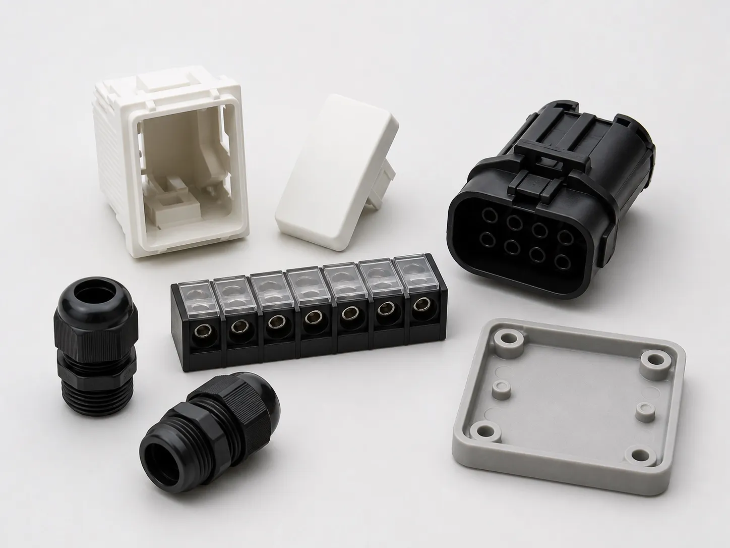
That matters on parts tested to Indian Standards. Under IS 1293 and IS 3854, plugs, socket-outlets and switches face mechanical strength and normal operation tests, including a plug inserted and withdrawn 10,000 times. Contact cavities that vary from shot to shot make that test harder to pass every time.
How does the controller switch from filling to holding?
During filling the motor runs under speed control, following the injection speed profile against screw position. At the set transfer point, usually a screw position, the controller switches to pressure control and the motor delivers the torque needed to hold the set plastic pressure, read from the load cell.
Because position comes from the encoder and the screw lead, the transfer point lands in the same place shot after shot. Holding pressure is then a torque command, so it does not sag as oil heats up through the shift. Cushion, the melt left in front of the screw after holding, becomes a steady number you can set limits on.
What can still go wrong with a ball screw drive?
The ball screw needs lubrication and inspection, the load cell needs a correct zero, and the screw, barrel and check ring wear as on any machine. Running a small screw at very high pressure for long periods also loads the ball screw hard, so respect the rated pressure.
Thomson's guidance is plain: never run a ball screw without proper lubrication, check for metal fragments and any change in noise or feel, and measure lash to track wear. On an injection unit, add a check of the load cell reading with the screw unloaded at start-up.
Our flat opinion: if part weight drifts on an electric injection unit, check the non-return valve before blaming the drive. A worn check ring lets melt slip back during holding, and no amount of servo accuracy can recover a shot that leaks backwards.
What should you ask a supplier about the injection drive?
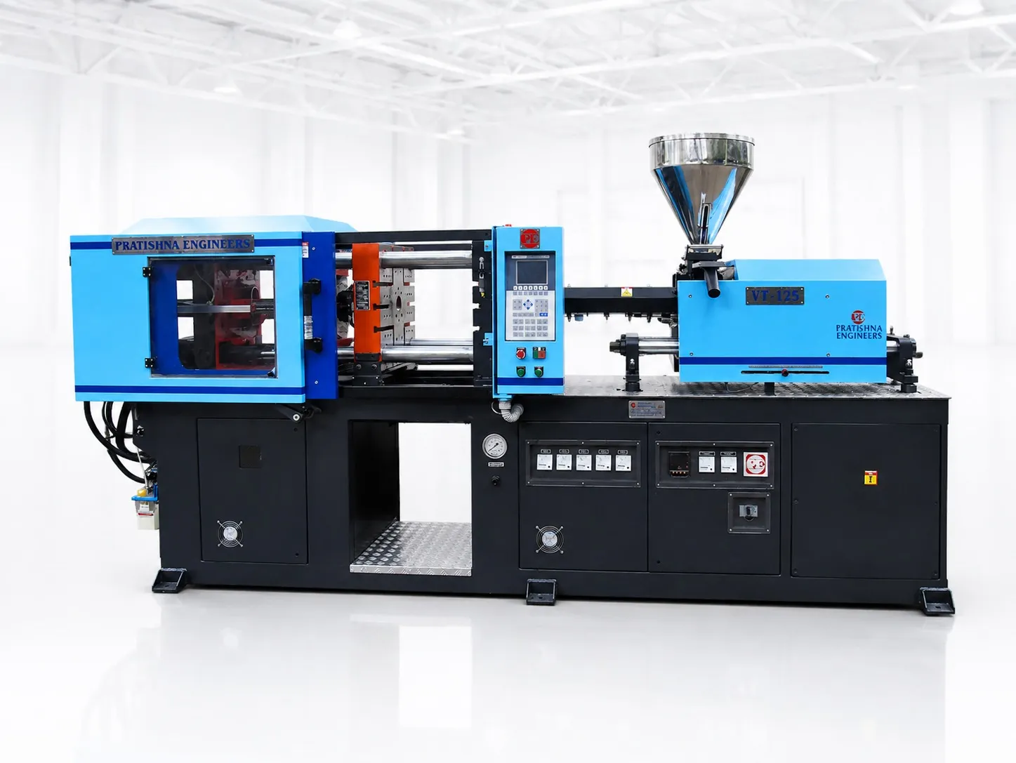
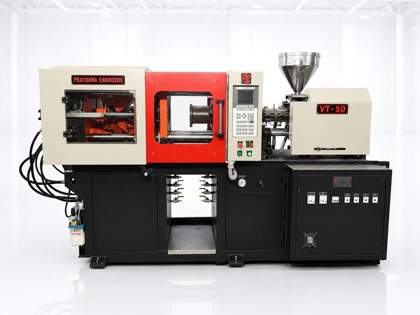
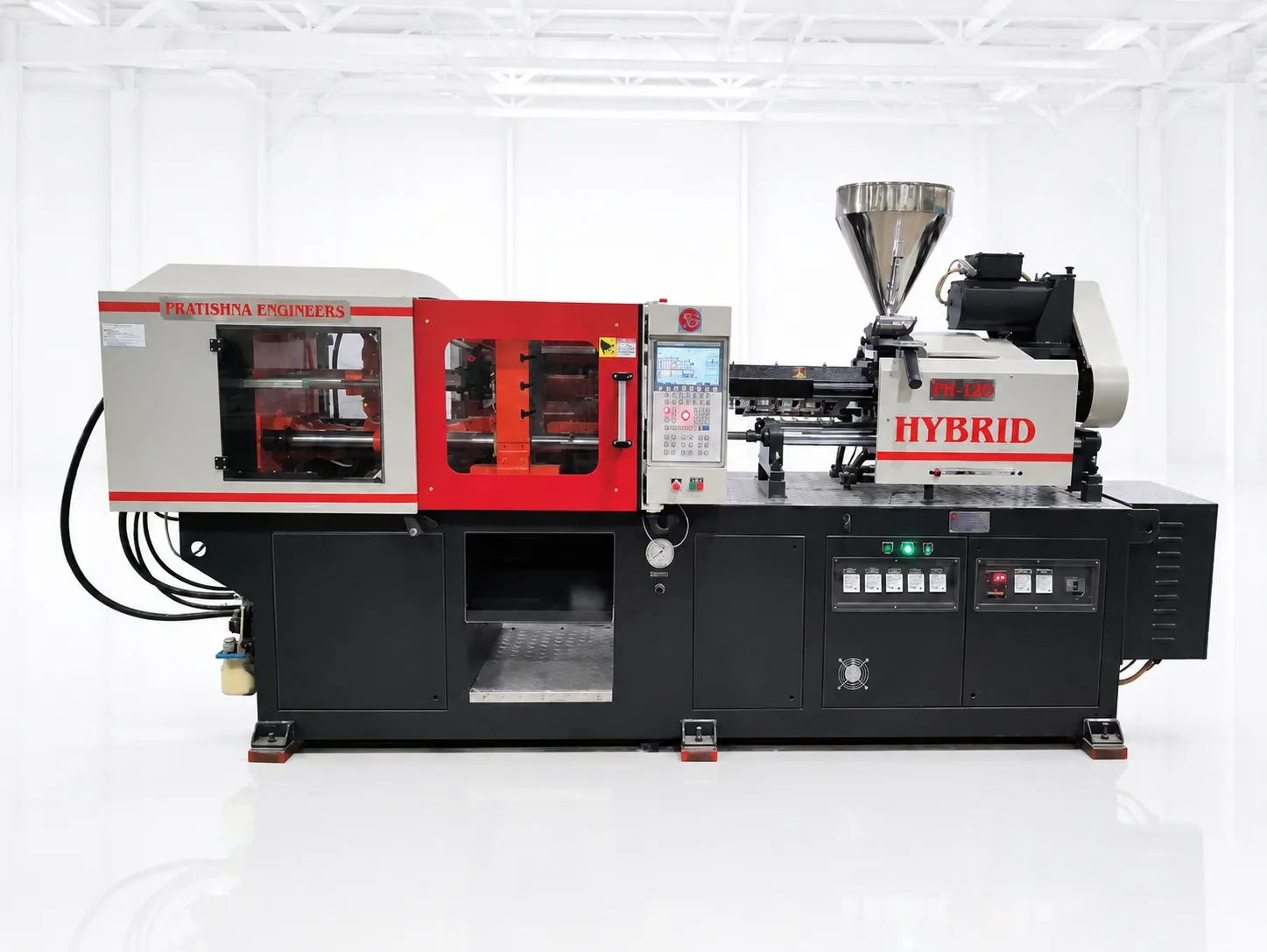
Ask for the injection pressure at each screw size, the maximum injection speed, how pressure is measured, the ball screw lubrication method and interval, and what the screen shows for actual speed, position and pressure each shot. Compare options on the hybrid injection moulding machine page.
Frequently Asked Questions About Ball Screw Injection
What is the lead of a ball screw?
Lead is the distance the ball nut travels for one full turn of the screw. A 10 mm lead moves the nut 10 mm per revolution. A shorter lead gives more thrust for the same motor torque but needs more revolutions for the same speed; a longer lead does the opposite.
Why is there a belt between the motor and the ball screw?
A belt and pulleys act as a fixed reduction. They multiply motor torque and let the motor sit beside the screw instead of behind it, which shortens the injection unit. Some designs mount the motor directly. Either way, the reduction ratio appears in every torque and speed calculation for the drive.
How is back pressure controlled on an electric injection unit?
During recovery the screw rotates and melt pushes it backwards. The injection motor resists that movement, and the load cell reading tells the controller how hard to resist. Raising the set back pressure makes the motor hold back more firmly, which improves mixing and melt density at the cost of longer recovery.
Does an injection load cell need calibration?
Yes. A load cell is a strain gauge sensor, and its zero can shift over time or after a crash. Check the reading with the screw unloaded at start-up, and have it calibrated at the intervals in the machine manual or after any mechanical work on the injection unit.
Can a ball screw unit reach the same pressure as hydraulic injection?
It can, if the ball screw, bearings and motor are sized for the thrust. Pressure at the melt equals thrust divided by screw area, so a smaller screw gives more pressure for the same thrust. Compare pressure figures at the screw size you will actually run, not the highest figure listed.
Related Articles
- What Is a Hybrid Injection Moulding Machine?
- Hybrid vs Hydraulic vs All-Electric Injection Moulding Machines
- Important Specifications to Consider Before Buying a Hybrid Machine
- Applications of Hybrid Injection Moulding Machines
Sources & References
- Thomson Industries, T. McNier and J. G. Johnson: Specifying, Selecting and Applying Linear Ball Screw Drives
- PlasticsToday (IMI): Sensor Technology on All-Electric Machines (Oct 1998)
- Plastics Technology, J. Bozzelli: Understanding Intensification Ratio (2016, updated 2022)
- BIS Blog, N. Agarwal: Standards for Plugs-Socket-Outlets and Switches (Feb 2023)
Technical Disclaimer
Disclaimer: The information provided in this document is for general informational and educational purposes only. It is based on technical references and industry information available at the time of preparation and may be subject to change. It does not constitute engineering, technical, commercial or professional advice, nor does it constitute a quotation, specification, warranty or contractual commitment by Pratishna Engineers.
Actual injection moulding machine and process requirements vary according to the component design, material, mould, production volume, machine configuration and operating conditions. The information, examples, calculations and recommendations provided should be independently evaluated and verified for the specific application before making any equipment, process or production decision. Information obtained from third-party sources remains subject to the accuracy and limitations of those sources.
Limitation of Liability: Pratishna Engineers makes no representation or warranty, express or implied, regarding the completeness, accuracy or suitability of the information for any particular application. To the extent permitted by applicable law, Pratishna Engineers shall not be liable for any loss, damage, cost or consequence arising from reliance on or use of the information contained in this document. Final machine selection, configuration and application suitability should be confirmed with Pratishna Engineers based on complete and accurate project requirements.