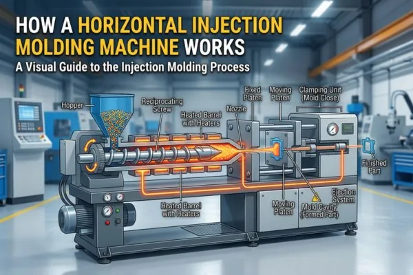

Horizontal injection moulding machine working: one cycle, stage by stage
| Stage | What the machine does | What sets the time |
|---|---|---|
| 1. Close and lock | The moving platen travels along the tie bars, slows near the parting line, then the clamp builds full force. | Opening stroke, mould protection setting |
| 2. Inject (fill) | The screw moves forward without turning and pushes melt through the nozzle into the cavity under speed control. | Injection speed, shot volume |
| 3. Pack and hold | The controller switches to pressure control and adds melt as the part shrinks, until the gate freezes. | Gate size, wall thickness |
| 4. Plasticise (screw recovery) | The screw turns and slides back, melting the next shot and collecting it in front of the tip. | Shot size, screw speed, back pressure |
| 5. Cool | The part stays in the closed mould until it is stiff enough to eject. | Wall thickness, mould temperature, water flow |
| 6. Open and eject | The mould opens sideways, ejector pins push the part out, and it drops or a robot picks it. | Opening and ejection stroke, part removal |
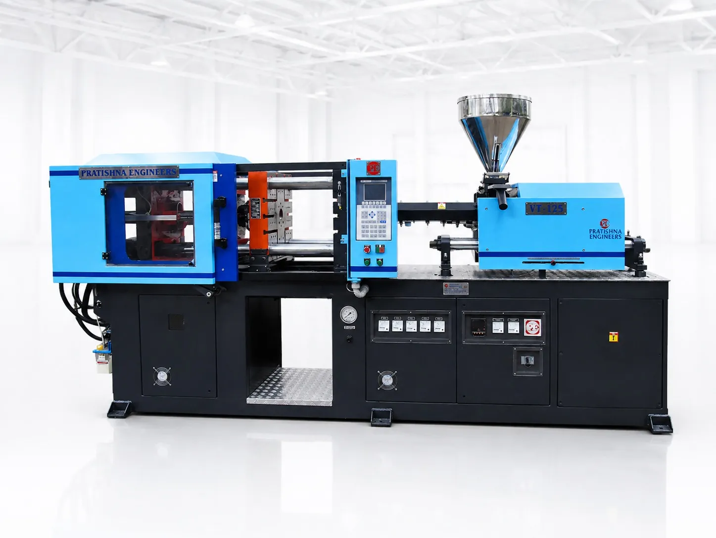
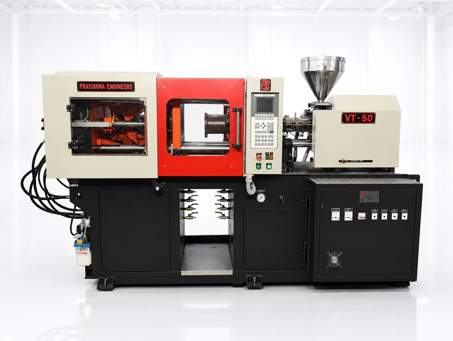
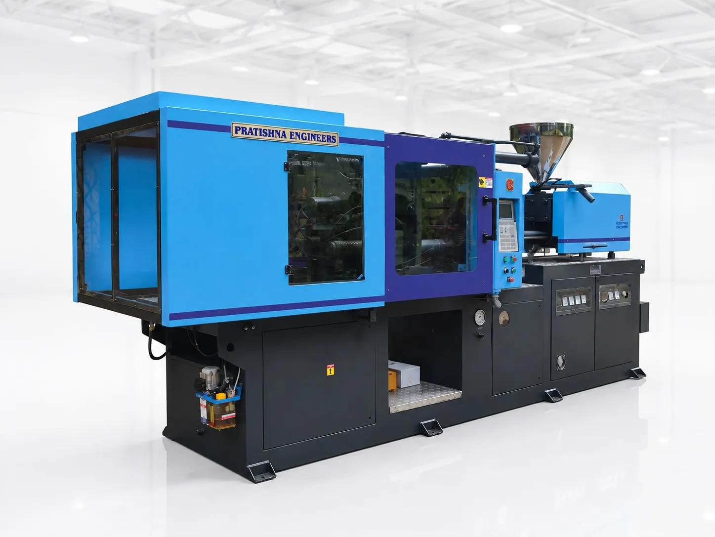
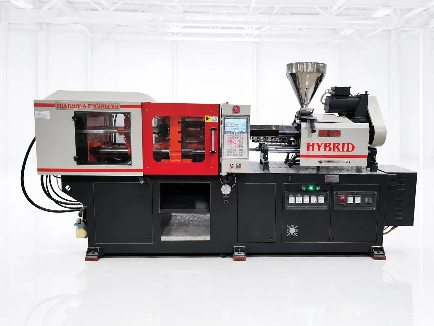
A horizontal injection moulding machine works by repeating one cycle. A screw melts plastic granules in a heated barrel, a clamp locks the two mould halves together on a horizontal axis, and the screw injects the melt. The machine then packs and cools the part before the mould opens sideways and the part is ejected. Each stage is set on the controller, and each one depends on your mould and material.
This article follows a single shot through the machine, from the hopper to the drop chute.
Key Takeaways
- The screw does two jobs. It turns and slides back to melt the next shot, then moves forward like a plunger to inject it.
- A toggle clamp multiplies a modest cylinder or servo force into full tonnage as its links straighten, which is why toggle machines suit fast cycles.
- Switch from speed control to pressure control when the cavity is about 95 to 98% full, then hold pressure until the gate freezes.
- Cooling time rises with the square of wall thickness, so a part with double the wall needs roughly four times the cooling.
- Keep the shot below about 65% of barrel capacity and above about 30% of the metering volume, and size the barrel with melt density, not solid density.
What Happens Inside the Barrel Before Each Shot?
Granules fall from the hopper into the feed zone of a rotating screw. Heater bands and friction melt them as the screw flights compress the material, and the melt collects in front of the screw tip. That melt pushes the screw backwards until it reaches the set shot size, and then the screw stops turning.
Most injection screws have three zones. The feed zone, roughly half the screw length, carries cold granules forward and squeezes out air. The compression or transition zone has a shrinking flight depth, so the material is pressed against the hot barrel wall and melts. The metering zone, with shallow and constant flights, evens out melt temperature before the melt passes the non-return valve. Covestro's processing guide for its polycarbonate and TPU grades recommends a length to diameter ratio (L/D) of 20 to 23, while Evonik's polyamide guide gives 18 to 22. The ranges overlap, so either is a fair reference for general work.
The non-return valve, usually a sliding check ring at the screw tip, lets melt flow forward while the screw turns and seals when the screw moves forward to inject. Evonik suggests keeping the gap between the valve and the barrel below 0.02 mm. When the ring wears, melt slips back during injection and shot weight drifts.
Check the ring before you blame the material.
Moisture enters at this stage too. Nylon is hygroscopic, which means it absorbs water from the air, and BASF lists a maximum of 0.15% moisture for its Ultramid B3G4 grade with drying at 80 °C for about 4 hours. During the monsoon in Mumbai or Chennai, an open bag beside the machine sits in humid air for the whole shift, so a dehumidifying dryer on the hopper isn't an accessory. It's part of the injection unit.
How Does the Clamp Open, Close and Lock the Mould?
The fixed platen holds the injection half of the mould and the moving platen carries the ejector half. Four tie bars guide the moving platen. A toggle linkage or a hydraulic cylinder drives it closed, slows it near the parting line to protect the mould, then builds the rated clamp force before injection starts.
On a toggle machine, a hydraulic cylinder or a servo-driven ball screw pushes a crosshead. The crosshead connects to the moving platen through pairs of hinged links. As the links straighten, their mechanical advantage climbs steeply, so a modest push at the crosshead becomes a very large force at the platen. At full lock the links are almost in line and the tie bars stretch slightly, which keeps the mould shut mechanically during injection. YIZUMI describes the same principle as high clamp force from low hydraulic pressure, and a Nirma University project report models it as the force amplification ratio of a five-point double toggle.
A two-platen machine has no linkage. Hydraulic cylinders apply the clamp force directly once the platen is in position, which keeps the machine shorter for a given mould size. Toggle machines still win on speed for smaller, high-volume parts.
Toggle clamp vs two-platen hydraulic clamp: pros and trade-offs
| Point | Toggle clamp | Two-platen hydraulic clamp |
|---|---|---|
| How force is made | Links straighten and multiply a small crosshead force | Hydraulic cylinders press the platens directly |
| Main strength | Fast opening and closing, low pressure needed to hold lock | Shorter machine for large moulds, force set directly |
| Trade-off | Clamp force depends on correct mould height setting and link condition | Longer pressure build-up, more oil volume under pressure |
| Typical fit | Small to medium moulds, high-volume cycles | Large, deep or heavy moulds |
More tonnage isn't better. An RJG column in Plastics Technology describes a mould that needed about 100 tons being run at the machine maximum of 400, and lists the damage excess force can do to the mould and the machine. Set clamp force from the mould's needs, not from the nameplate.
What Drives the Screw and the Clamp?
On a hydraulic machine, an electric motor drives a pump that sends oil to the clamp, injection and ejector cylinders and to the hydraulic motor that turns the screw. A servo-hydraulic machine runs the pump with a servo motor that slows down when demand drops. An all-electric machine uses a separate servo motor for each axis.
The difference shows up during cooling, when little moves. A fixed-speed pump keeps turning, and a servo pump doesn't have to. Any saving depends on your cycle, so ask for measured kWh per kg on a comparable mould rather than a headline percentage.
What Happens During Injection, Packing and Holding?
Injection fills most of the cavity under speed control. At roughly 95 to 98% full, the controller switches to pressure control. Pack pressure then adds the melt needed to make up for shrinkage, and hold pressure keeps it there until the gate freezes.
The switch point is called velocity to pressure transfer, or V/P transfer. RJG sets it with a fill-only part, a shot made with pack and hold turned off, which should look about 95 to 98% full. If it's already full, injection speed is doing the packing, and you'll see flash and unstable weight.
Gate freeze is found by weighing. Paulson Training describes moulding parts at increasing hold times and plotting part weight against time. When the weight stops rising, the gate has sealed, and extra hold time only lengthens the cycle.
Part weight is the simplest daily check that pack and hold are working.
Recycled polypropylene (PP) makes this harder. AIMPLAS notes that melt flow index can vary widely between batches of recycled resin, which shifts the fill at a fixed setting. If you buy recycled PP from different reprocessors, recheck the fill-only part whenever a new lot is opened.
Why Does Cooling Decide Most of the Cycle Time?
The part can't be ejected until it's stiff enough to resist the ejector pins. Heat has to travel from the middle of the wall into the mould steel and the cooling water. Because that time grows with the square of wall thickness, cooling is usually the longest stage.
Sources don't agree on how long. DME, a mould component maker, puts cooling at typically 50% of the cycle in its cooling channel literature, while several moulding service providers quote 70 to 80%. We use the DME figure as a planning number because it comes with measured cycle comparisons, and we treat higher shares as typical of thick-walled parts. The wall thickness rule holds either way. Design World points out that thickness is squared in the cooling equation, so moving from a 2 mm wall to a 3 mm wall multiplies cooling time by about 2.25 if everything else stays the same.
Water quality is the shop-floor side of this. A 2024 study of 290 groundwater sites in Uttar Pradesh found total hardness above the permissible limit in about a quarter of samples. Hard make-up water in a cooling tower leaves insulating scale in mould channels, and DME reports one mould whose cycle rose from 18 to 26 seconds before cleaning.
Screw recovery runs during cooling. If the screw can't melt the next shot within the cooling time, recovery becomes the bottleneck, which usually means the injection unit is too small for the job.
How Are Parts Ejected and Removed on a Horizontal Machine?
Once the clamp opens, the ejector pushes a plate in the moving mould half, and pins or a stripper plate push the part off the core. Because the mould opens sideways, the part can fall into a chute or onto a conveyor, or a robot can pick it.
That gravity drop is the main reason horizontal machines suit long unattended runs. Parts that must not be scratched are better picked by a robot. YIZUMI also points out that a horizontal line takes more floor space once the robot, conveyor, dryer and loader are added.
The mould area is guarded. ISO 20430:2020 sets safety requirements for injection moulding machines with hydraulic or electrical platen drives. We read the scope published by ISO, not the full clause text, so check the current edition and its status in India before you treat any clause as binding.
What Must the Machine Provide for Your Part?
The machine has to deliver enough melt for the whole shot, hold the mould shut against injection pressure, accept the mould between its tie bars, and open far enough to release the part. Each of these comes from the part and mould, so don't compare machines until they're worked out.
What the machine must provide and how to work it out
| Requirement | How to work it out | Reference rule (from cited sources) |
|---|---|---|
| Shot volume | (Part weight × cavities + cold runner weight) ÷ melt density | Keep the shot below about 65% of barrel capacity (Plastics Technology) and above about 30% of metering volume (Evonik) |
| Shot rating | Ratings are often quoted for polystyrene (PS), so convert with melt densities | PS melt density 0.945 g/cm³, PP about 0.74 g/cm³ (Plastics Technology) |
| Clamp force | Total projected area of parts and cold runner × tonnage factor | 2 to 10 US tons/in², with 3 tons/in² as a starting point (RJG) |
| Tie-bar spacing | Mould width and height against the clear distance between tie bars | The mould must pass between the bars or be loaded from a side the bars allow |
| Mould height | Mould shut height | Must sit between the minimum and maximum mould thickness of the clamp |
| Opening stroke | Part depth, ejection stroke and room for the part to fall or be picked | Check against the mould drawing and the removal method |
| Screw design | Material and additives | L/D 20 to 23 (Covestro) or 18 to 22 (Evonik), check ring gap below 0.02 mm (Evonik) |
What Usually Goes Wrong in Horizontal Injection Moulding Machine Working?
Most faults trace back to one stage running out of step with the others. The melt may be wet, the switch to packing may come late, the clamp may be set wrong, or scale may be starving the cooling. The table shows where to look first.
Troubleshooting by machine stage
| Defect | Possible causes | Effect on the part | Areas to investigate |
|---|---|---|---|
| Short shot | Shot size too small, worn check ring, V/P transfer too early, low melt temperature | Incomplete part, rejection | Fill-only part, cushion, check ring, barrel temperatures |
| Flash | Clamp force too low for projected area, V/P transfer too late, damaged parting line | Thin film at the parting line, extra trimming | Tonnage calculation, transfer position, mould faces |
| Sink marks or voids | Pack or hold too short or too low, gate freezing early, thick sections | Surface depressions, internal voids | Gate freeze study, hold profile, wall design |
| Splay or silver streaks | Moisture in nylon or other hygroscopic resin, overheated melt | Streaks on the surface, lower strength | Dryer temperature and time, residence time in the barrel |
| Weight drifts shot to shot | Worn check ring, varying melt flow in recycled resin | Dimensional variation | Cushion stability, lot changes, part weight log |
| Cycle creeps up over months | Scale in mould channels or heat exchangers | Lower output, warpage | Water flow and temperature rise across the mould, water hardness, descaling |
What Should You Send Before Choosing a Horizontal Machine?
Send the part drawing or a sample, the material grade, part and runner weight, the number of cavities, the mould's outside size and shut height, and your monthly volume. With those, the shot volume, clamp force and mould-fit checks in this article can be worked out before any machine is named. You'll find how these requirements map to machine layouts on the horizontal injection moulding machine page.
Frequently Asked Questions About Horizontal Injection Moulding Machine Working
What is the difference between plasticising and injection?
Plasticising is the melting stage. The screw turns, draws granules from the hopper, melts them and collects the next shot in front of its tip while sliding backwards. Injection is the next stage, when the screw stops turning and moves forward like a plunger to push that melt into the mould. On most machines plasticising for the next shot runs during cooling of the current one.
Why is it called a reciprocating screw?
The screw moves back and forth along the barrel as well as turning. It slides back while it melts and meters the shot, then moves forward to inject it. Because the material is sheared as well as heated while the flights carry it forward, the melt reaches the tip better mixed than barrel heat alone would leave it.
What does the check ring on the screw do?
The check ring is a non-return valve at the screw tip. It lets melt pass forward while the screw turns and closes when the screw moves forward, so the melt goes into the mould instead of back along the flights. A worn ring causes short shots and drifting part weight. Evonik suggests keeping the gap between valve and barrel below 0.02 mm.
How does a toggle clamp create so much force?
A toggle clamp uses hinged links between a crosshead and the moving platen. As the links straighten, a small movement of the crosshead produces a large force at the platen, the same principle as a knee joint locking straight. At full lock the tie bars stretch slightly and the links hold the mould shut mechanically, with little hydraulic pressure needed to keep it locked.
What is V/P transfer in injection moulding?
V/P transfer is the point where the machine stops controlling injection by speed and starts controlling it by pressure. It's usually set so the cavity is about 95 to 98% full when the switch happens. Transferring too late overpacks the part and can cause flash. Transferring too early can leave short shots that hold pressure alone can't fill.
How long should hold pressure be applied?
Hold pressure should last until the gate freezes, plus a small margin. Find that point by moulding parts at increasing hold times and weighing them. When part weight stops increasing, the gate has sealed. Holding longer than that adds cycle time without adding material, and stopping earlier lets melt flow back out of the cavity, which causes sink marks and weight variation.
Why are horizontal machines preferred for automatic production?
The mould opens sideways, so an ejected part can fall under gravity into a chute, a box or onto a conveyor. That makes long unattended runs practical without an operator at the gate. Where parts must not be scratched or must be placed in order, a robot picks them from the parting line instead. Both routes keep the cycle running without manual removal.
How do I know if the barrel is the right size for my shot?
Work out the total shot weight, including any cold runner, and divide it by the melt density of your plastic to get shot volume. Plastics Technology warns that shots above about 65% of barrel capacity tend to melt unevenly, and Evonik suggests using at least about 30% of the metering volume. Don't forget that machine ratings are often quoted for polystyrene.
Why does my cycle time increase over months on the same mould?
A common cause is scale building up in the mould cooling channels or the machine heat exchangers. Scale insulates, so heat leaves the part more slowly and cooling time has to be extended. Hard water in an open cooling tower speeds this up. Check water flow and the temperature rise across the mould, and descale the channels on a fixed schedule.
Is clamp force the same as machine tonnage?
Machine tonnage is the maximum clamp force the machine can deliver. The force a mould needs is usually lower, and it isn't fixed by the nameplate. It comes from the projected area of the parts and cold runner multiplied by a tonnage factor for the material. RJG suggests starting at 3 US tons per square inch. Running far above the need can damage the mould and the machine over time.
Verified Key Facts
- Screw length to diameter ratio (L/D) of 20 to 23 for polycarbonate and TPU grades (Covestro), and 18 to 22 for polyamide grades (Evonik).
- Gap between the non-return valve and the barrel below 0.02 mm as a rule of thumb (Evonik).
- Shots above about 65% of barrel capacity tend to give melt-quality problems (Plastics Technology). Use about 30 to 70% of the maximum metering volume (Evonik).
- Melt density about 0.74 g/cm³ for PP and 0.945 g/cm³ for PS (Plastics Technology).
- Tonnage factors of 2 to 10 US tons/in², with 3 tons/in² as a starting point (RJG, Plastics Technology).
- Velocity to pressure transfer when the cavity is about 95 to 98% full (RJG).
- Cooling time scales with the square of wall thickness (Design World).
- Cooling is typically about 50% of the moulding cycle, and one scaled mould went from 18 to 26 seconds (DME).
- Ultramid B3G4 nylon: maximum 0.15% moisture, pre-drying at 80 °C for 4 hours (BASF, via Material Data Center).
- Total hardness above the permissible limit in 24.48% of groundwater samples from 290 sites in Uttar Pradesh (Journal of Hydroinformatics, 2024).
- ISO 20430:2020, Edition 1, published April 2020 and last reviewed and confirmed in 2025 (ISO).
Related Articles
- What Is a Horizontal Injection Moulding Machine?
- Horizontal vs Vertical Injection Moulding Machines: Key Differences
- Important Specifications to Consider Before Buying a Horizontal Injection Moulding Machine
- Applications of Horizontal Injection Moulding Machines
Sources & References
- ISO: ISO 20430:2020 Plastics and rubber machines, Injection moulding machines, Safety requirements
- Chaudhary S. et al., Journal of Hydroinformatics (2024): Characterization of groundwater potability and irrigation potential in Uttar Pradesh, India
- Nirma University: Toggle Clamp Linkages Design in Plastic Injection Moulding Machine (project report)
- BASF via Material Data Center: Ultramid B3G4 (PA6-GF20) datasheet
- Covestro: Injection molding of high-quality molded parts
- Evonik: Processing of TROGAMID molding compounds
- YIZUMI: Injection Molding Machine Clamping Systems: Toggle vs Two-Platen Compared
- YIZUMI: Vertical vs Horizontal Injection Molding Machine: Features, Pros, Cons, Applications, and How to Choose
- DME: CoolingCare brochure: cleaning, diagnostics and conservation of cooling channels
- AIMPLAS: Injection Molding of Recycled Thermoplastics: Strategies for a Stable Process
- RJG / Plastics Technology: Clamp Tonnage: More Is Better...Right?
- Plastics Technology (J. Bozzelli): A Simpler Way to Calculate Shot Size vs. Barrel Capacity
- RJG: Establishing a Fill Only Part: Sometimes Easier Said than Done
- Paulson Training: Scientific Injection Molding: Packing Pressure and Gate Seal
- Design World: Injection Molding Cooling Time: A Breakdown
Technical Disclaimer
Disclaimer: The information provided in this document is for general informational and educational purposes only. It is based on technical references and industry information available at the time of preparation and may be subject to change. It does not constitute engineering, technical, commercial or professional advice, nor does it constitute a quotation, specification, warranty or contractual commitment by Pratishna Engineers.
Actual injection moulding machine and process requirements vary according to the component design, material, mould, production volume, machine configuration and operating conditions. The information, examples, calculations and recommendations provided should be independently evaluated and verified for the specific application before making any equipment, process or production decision. Information obtained from third-party sources remains subject to the accuracy and limitations of those sources.
Limitation of Liability: Pratishna Engineers makes no representation or warranty, express or implied, regarding the completeness, accuracy or suitability of the information for any particular application. To the extent permitted by applicable law, Pratishna Engineers shall not be liable for any loss, damage, cost or consequence arising from reliance on or use of the information contained in this document. Final machine selection, configuration and application suitability should be confirmed with Pratishna Engineers based on complete and accurate project requirements.