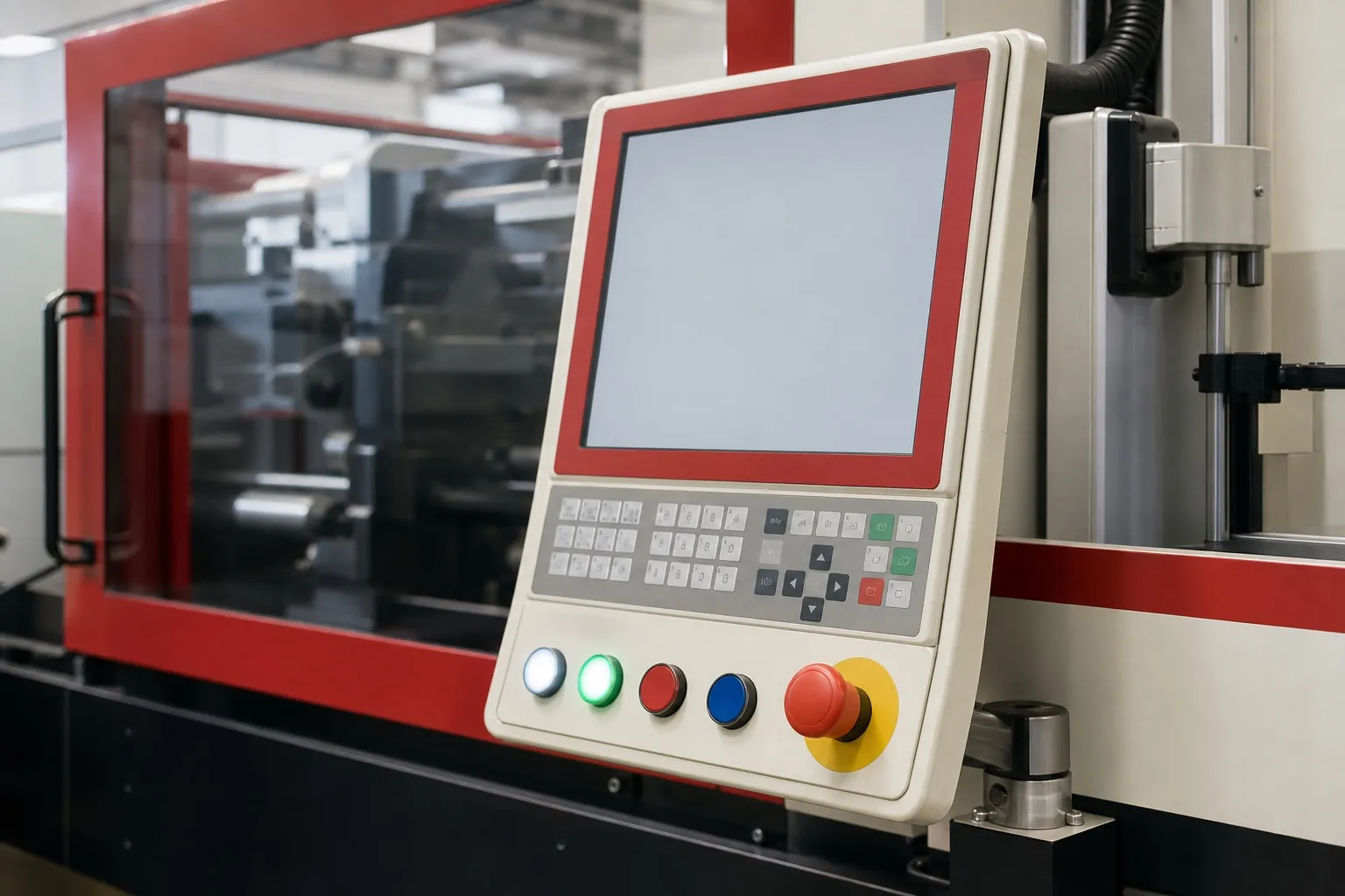

Four ways to load a small insert cell, from hand loading to insert moulding automation
| Arrangement | How it works | What sets the cycle | Fits |
|---|---|---|---|
| Fixed lower mould, hand loaded | Operator unloads parts and loads inserts while the mould is open | Moulding time plus loading time, end to end | Trials, short runs, many part variants |
| Sliding (shuttle) table, hand loaded | Two lower halves share one top half; one is loaded while the other is moulded | The longer of moulding or loading, plus the table move | Steady runs where loading takes about as long as moulding |
| Rotary table | Two or more lower halves index under the top half | The slowest station, plus the index | Parts with separate load, check and unload steps |
| Robot with feeder and vision | A feeder presents inserts, a robot loads and unloads, cameras check seating | The robot routine, which repeats shot to shot | High, steady volumes of one insert type |
That is the choice in one table. Hand loading costs least to set up and adapts to any part, but the cycle waits on the operator. A shuttle or rotary table hides loading inside the moulding time. Full automation takes the operator away from the mould and makes every cycle the same length.
The right answer depends on volume, insert type and how loading time compares with moulding time. Time those two first, separately, on a real mould.
Key Takeaways
- On a fixed mould, loading time adds to moulding time; a shuttle or rotary table lets the two overlap.
- A shuttle table needs two lower halves and one top half, and it hides loading time but not cooling time in the clamp.
- One case study describes 30 s of hand unloading, cavity checks and insert loading on a four-cavity mould, taken over by a robot, bowl feeder and vision.
- Waiting costs power: measured machines drew 52% to 97.5% of their full moulding energy while idling.
When Is Hand Loading the Right Choice?
When volumes are modest, part variants change often or inserts are awkward to feed automatically. Hand loading needs no feeder, no robot and only one lower mould half, so a new part starts with the least spend. The price is a longer cycle that varies with the operator.
That variation matters more than it looks. A Robotic Industries Association case study notes that consistent mould-open times eliminated mould temperature fluctuations. When an operator takes 20 s on one shot and 30 s on the next, the mould cools by different amounts, and part dimensions can drift with it.
Hand loading also means hands inside the mould area every cycle. Guarding, interlocked doors or two-hand controls and a clear view of the lower mould are part of the cell design, not extras.
Our view: start a new insert part on hand loading with a fixed lower mould, record a few hundred real cycles, and only then decide on a shuttle table or a robot. Measured loading data beats any estimate made at the quotation stage.
How Does a Shuttle or Rotary Table Shorten the Cycle?
By letting the operator load one lower mould half while the other is in the clamp. A PlasticsToday article describes the conventional layout: one top half and two bottom halves. Loading then overlaps moulding, so the cycle follows whichever takes longer, plus the time to move the table.
There is a limit. The same article notes that the machine still has to wait for each part to cool in the clamp before it moulds the next, so a table hides loading time but not cooling time. Thick parts with long cooling gain less from it.
The second lower half adds tooling cost, and both halves must match closely enough that parts from either side meet the drawing. Mark each half and track rejects by half, so a problem in one is found quickly.
A rotary table indexes two or more lower halves under the top half. It earns its place when a part needs more than one station, such as loading, checking and unloading, each at its own position.
What Does Insert Moulding Automation Add?
A feeder to present inserts, a robot to load them and unload parts, and checks that stop a bad shot before it is moulded. The payoff is a cycle that repeats exactly and fewer moulds damaged by misplaced inserts. The cost is engineering time and less flexibility between parts.
The RIA case study shows the pieces. A SCARA robot picks four parts and the runner, drops the runner into a scrap chute and places parts on a four-station index table for inspection. It loads inserts from a vibratory bowl feeder, and vision confirms that cavities are free of debris and inserts are seated before moulding.
Post-mould vision keeps bad parts inside the cell instead of in the shipment. That check is worth most on parts where a missing or tilted insert cannot be seen from outside.
Automation suits one insert type in high, steady volumes. Where inserts tangle, vary between batches or come in many sizes, the feeder may need its own development work, and a skilled operator may stay the better feeder.
What Does Waiting Cost in Power?
More than it seems. A machine waiting for an operator keeps its barrel heaters on, and a hydraulic machine with a fixed-speed pump keeps the pump turning. Measurements reported in PlasticsToday found idling machines drawing 52% to 97.5% of their full moulding energy.
The same article by Robin Kent suggests that idle periods longer than 1.5 hours may be cheaper to switch off and restart. It also notes that a clamp-meter data logger can measure a machine in as little as 30 minutes, which makes the waiting share of a hand-loaded cell easy to find.
In Maharashtra the bill adds another layer. MSEDCL's kVAh billing FAQ explains that demand charges are levied on kVA and energy charges on kVAh, and notes that at a power factor of 0.85, 15% of the power drawn does no useful work. Energy drawn while a machine idles is billed in kVAh like any other, so idle time shows up directly on the energy line.
How Should You Decide on the Loading Method?
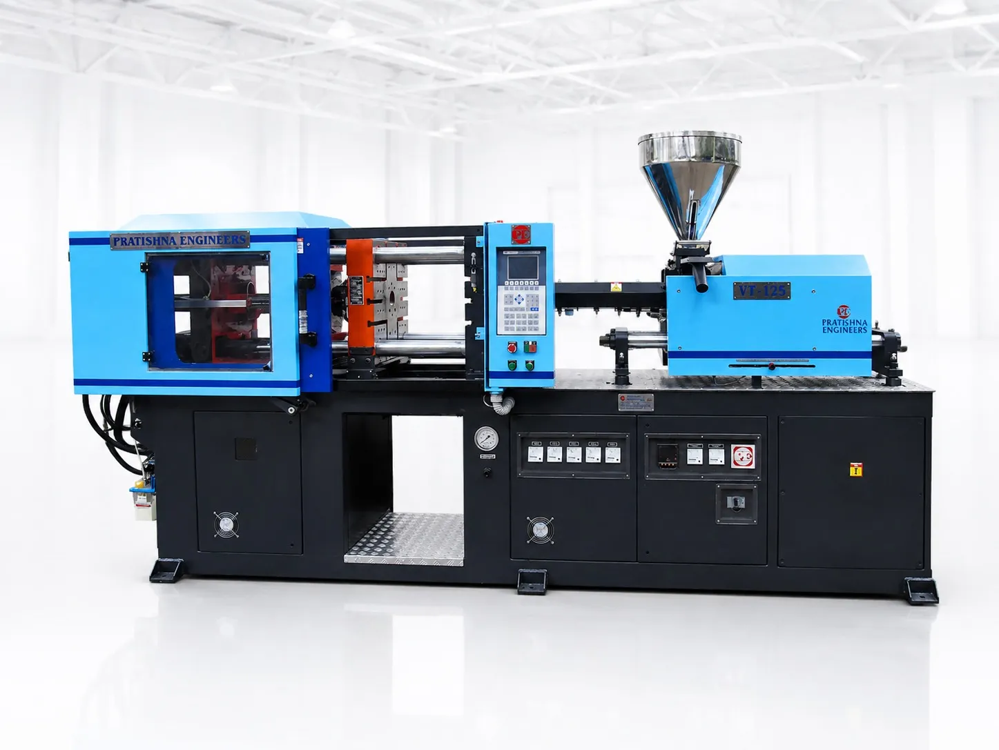
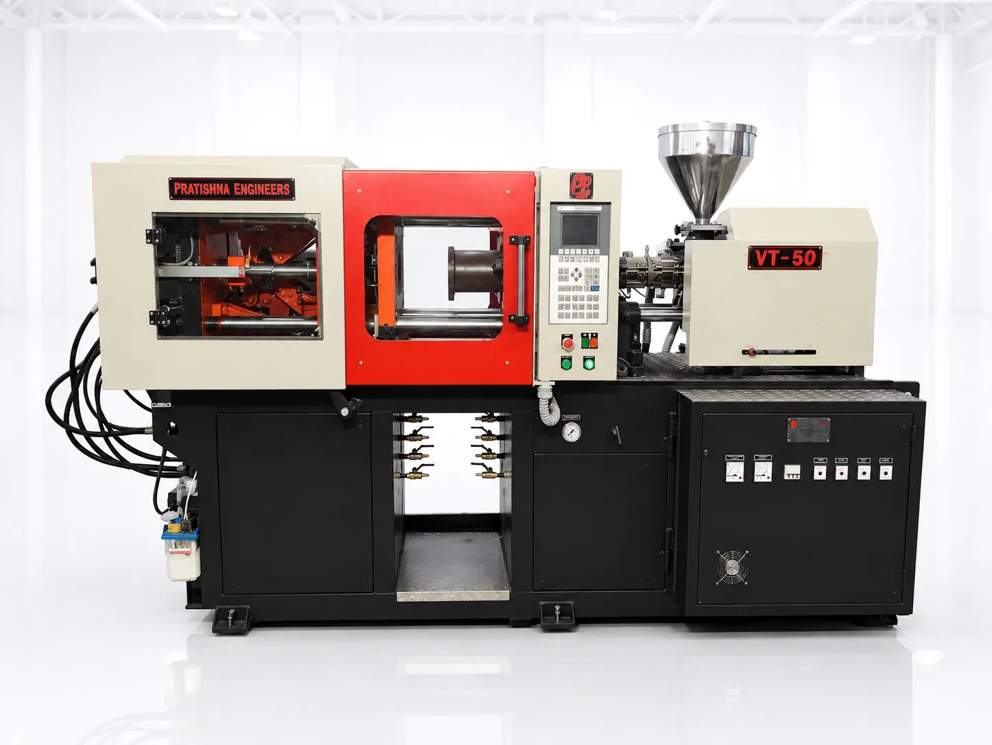
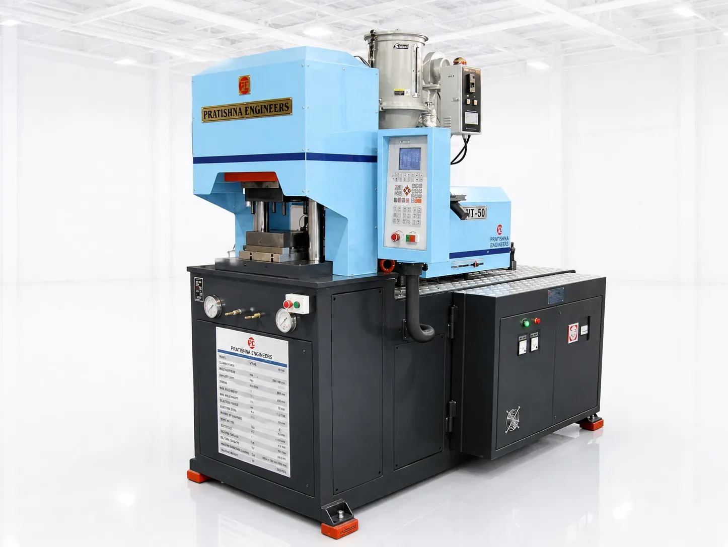
Time the moulding cycle and the loading routine separately on a trial mould, then set them against annual volume, the number of part variants and the insert type. Compare output per shift for each arrangement before pricing tooling or a robot. See the 40 ton vertical injection moulding machine page.
Frequently Asked Questions About Insert Loading Methods
Is a robot worth it for a single-cavity mould?
Sometimes. With one cavity, loading is quicker, so a robot saves fewer seconds per shot. It can still pay where operators are hard to find, inserts must be placed with care, or every cycle has to be the same length for dimensional control. Compare output and scrap with and without it.
How do I time loading for a quotation?
Copy the lower mould pockets in a simple fixture, give an operator real inserts and time at least 20 loads, including part removal and any checks. Use the average and the slow end of the spread. A single quick timing by an engineer will understate the real cycle on the floor.
What can go wrong with a bowl feeder?
Inserts can tangle, jam on the track or arrive the wrong way up if their shape is nearly symmetrical. A burr or an oil film on one batch can stop them feeding altogether. Trial the feeder with inserts from several batches before committing, and keep a manual loading fixture as a fallback.
Does a shuttle table change what the machine must provide?
Yes. It needs a lower platen or table long enough for two lower halves, accurate positioning of each half under the top half, and safety interlocks at both load stations. Confirm the table travel and the largest lower half it accepts before the mould design is frozen.
Can one operator run two hand-loaded machines?
Only if each machine's moulding time covers the loading and walking time at the other. With short cycles, one machine waits and both outputs fall. Time the combined routine on the floor before planning staffing around it, and keep the same guarding and safety checks at both machines.
Related Articles
- What Can You Make on a 40 Ton Vertical Insert Moulding Machine?
- Moulding Plug Pins and Terminals on a 40 Ton Vertical Machine
- Needle Hubs on Vertical Machines: Insert Location and Bond Strength
Sources & References
- PlasticsToday: Shuttle table increases production (Aug 2008)
- Robotic Industries Association via Smart Molding, J. Clark: Automated injection molding operation
- PlasticsToday, R. Kent: Getting to know your real energy use and cost (Jan 2010)
- MSEDCL: kVAh Billing: Frequently Asked Questions
Technical Disclaimer
Disclaimer: The information provided in this document is for general informational and educational purposes only. It is based on technical references and industry information available at the time of preparation and may be subject to change. It does not constitute engineering, technical, commercial or professional advice, nor does it constitute a quotation, specification, warranty or contractual commitment by Pratishna Engineers.
Actual injection moulding machine and process requirements vary according to the component design, material, mould, production volume, machine configuration and operating conditions. The information, examples, calculations and recommendations provided should be independently evaluated and verified for the specific application before making any equipment, process or production decision. Information obtained from third-party sources remains subject to the accuracy and limitations of those sources.
Limitation of Liability: Pratishna Engineers makes no representation or warranty, express or implied, regarding the completeness, accuracy or suitability of the information for any particular application. To the extent permitted by applicable law, Pratishna Engineers shall not be liable for any loss, damage, cost or consequence arising from reliance on or use of the information contained in this document. Final machine selection, configuration and application suitability should be confirmed with Pratishna Engineers based on complete and accurate project requirements.