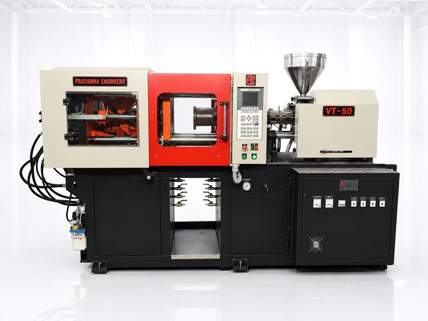
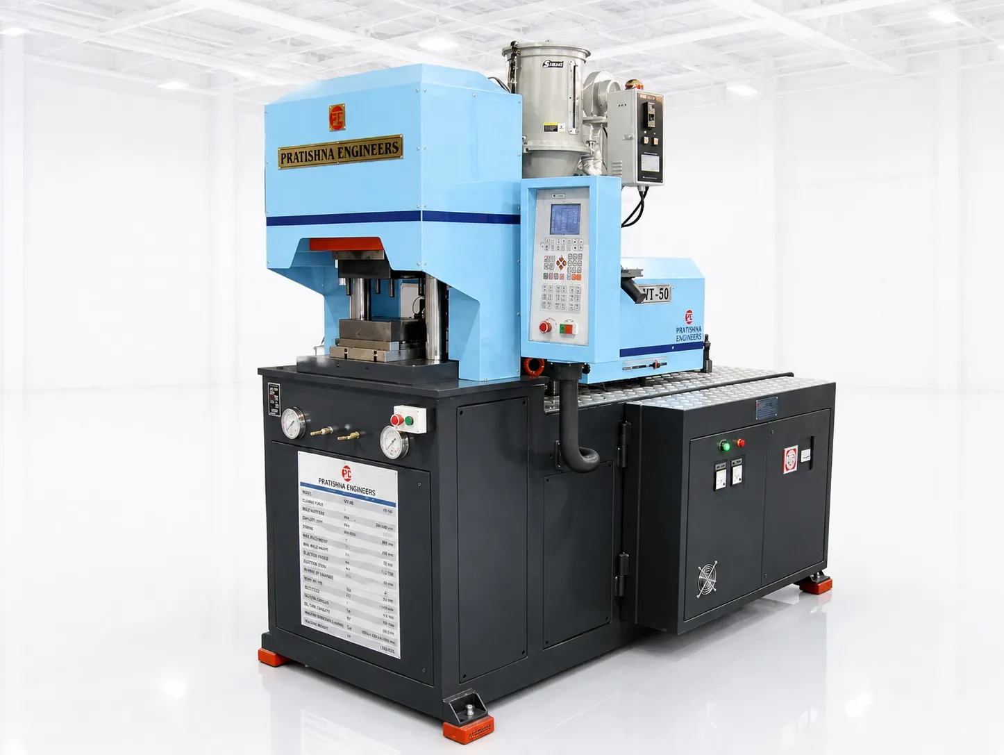
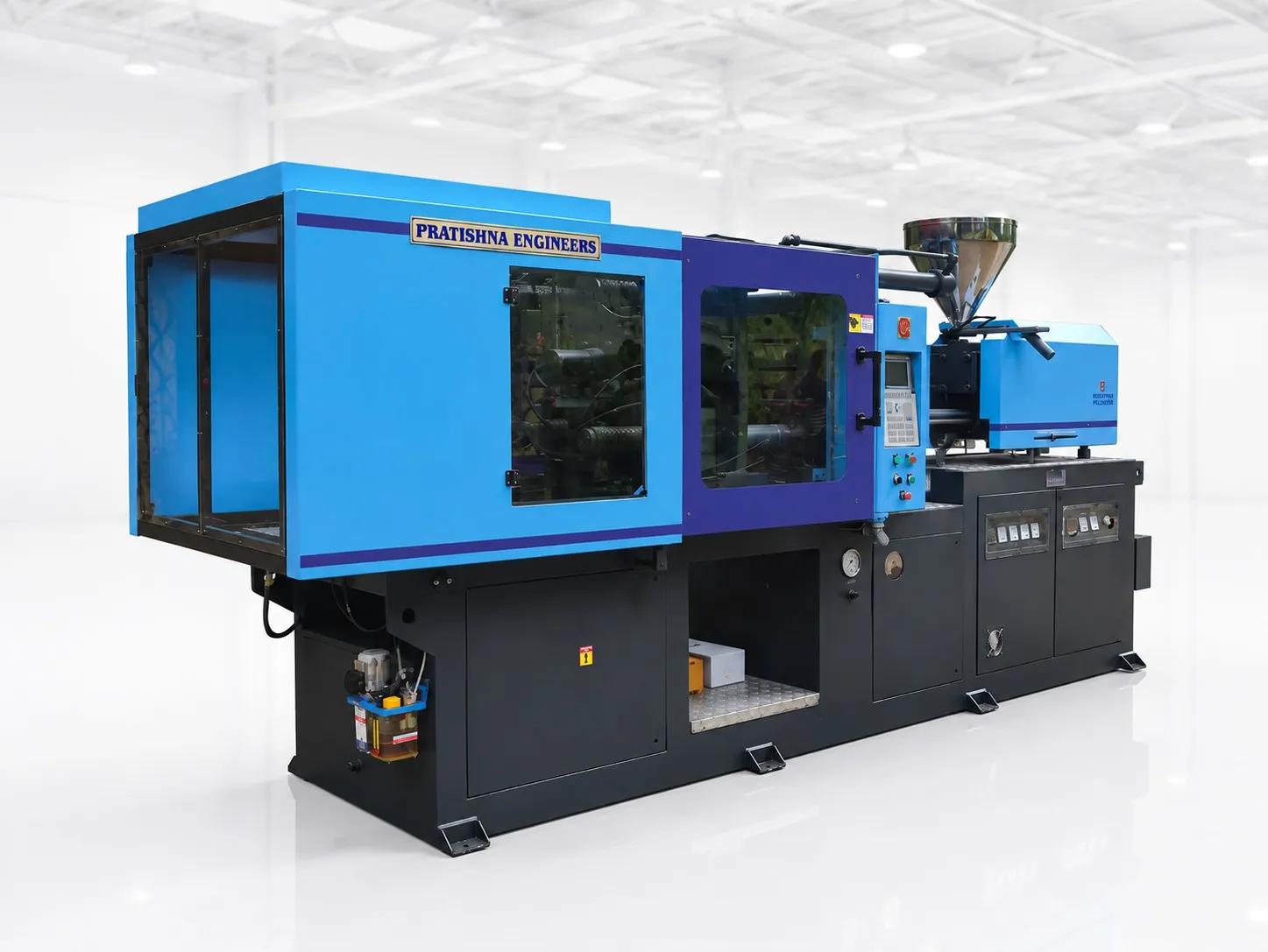
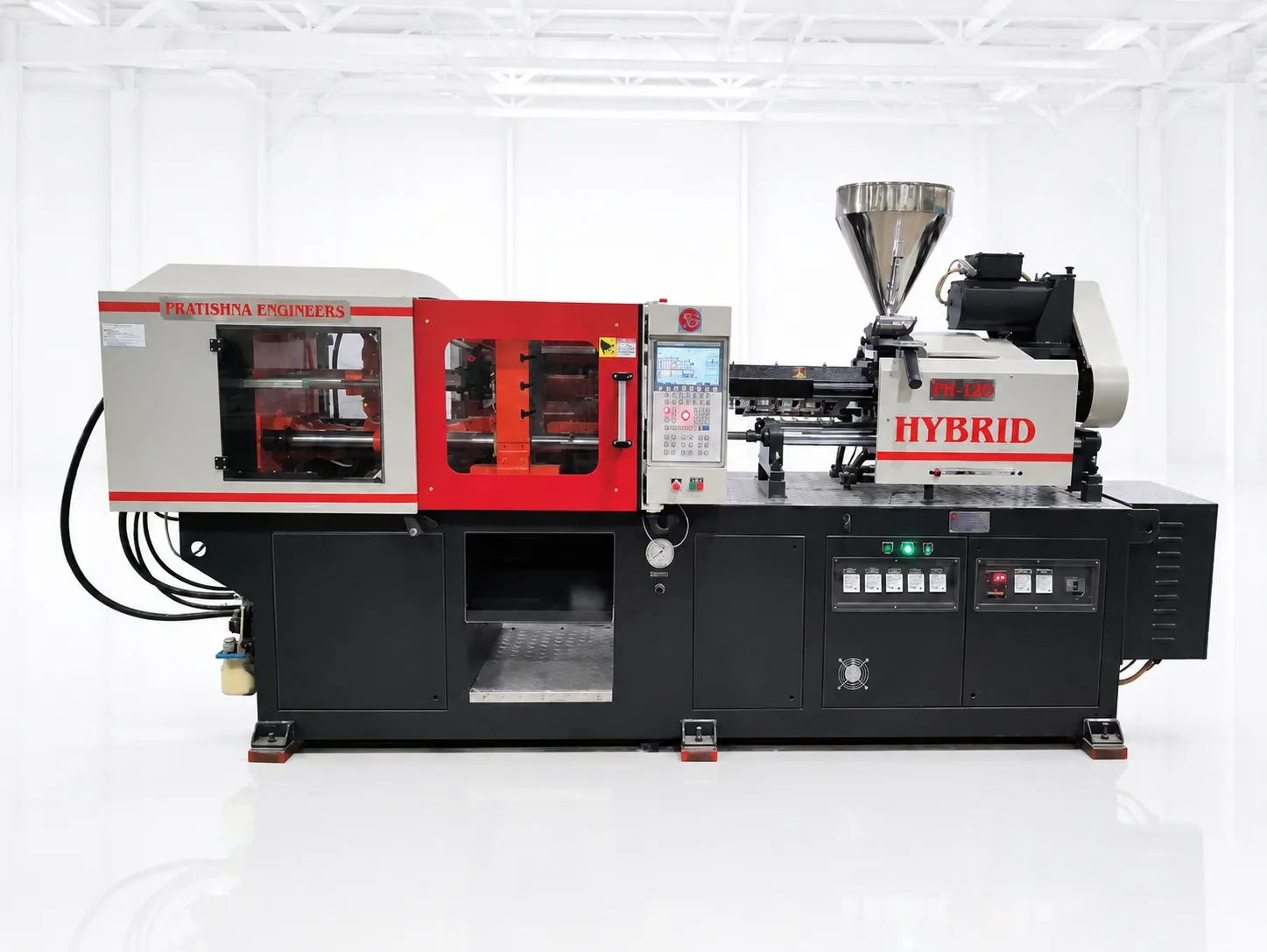

The operator drops two brass terminals into the lower mould half, reaches for the third, and the guard timer has already run out. The clamp waits. Ten minutes later a tilted terminal gets crushed and the mould goes to the toolroom. That is where an insert job is won or lost: not in the barrel, but in the seconds the mould stands open.
A sound insert moulding setup on a vertical clamp machine comes down to four things. Each insert seats in one position only. The operator can see and reach every pocket. Something confirms every insert is present before the clamp closes. And the loading time is measured, not guessed.
Key Takeaways
- A vertical clamp opens upward, so the lower half faces the operator and gravity helps each insert stay in its pin or pocket.
- Every insert needs one clear locating feature and a close fit to it; through inserts must also seal against both mould halves.
- Open-mould time equals inserts times placement time, plus part removal and checking. Measure it over a full shift, not a few cycles.
- An insert-present check before clamp close protects the mould, the part and the delivery date. Treat it as part of the setup.
Why do vertical clamp machines suit insert moulding?
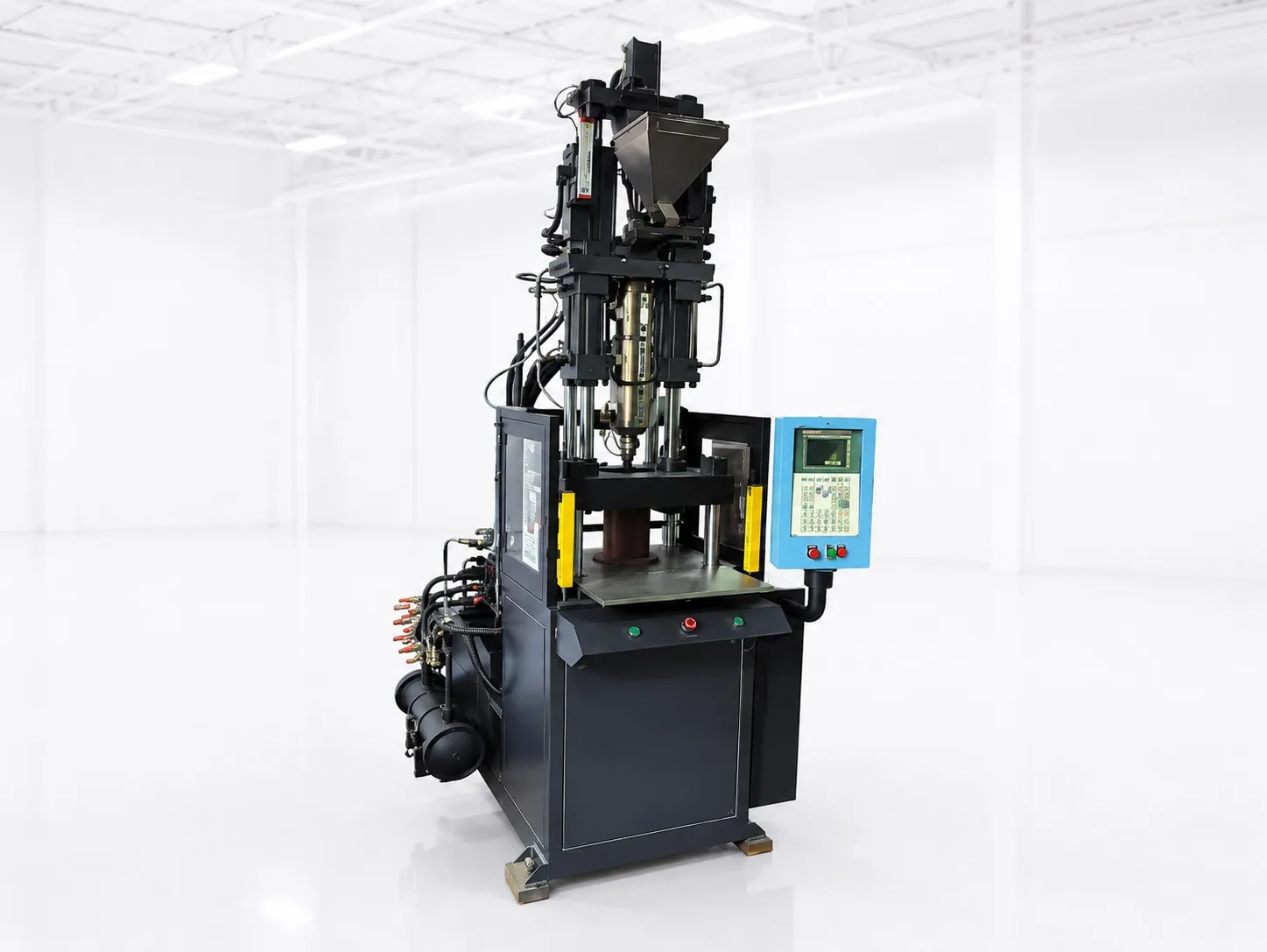
On a vertical clamp the lower mould half faces upward. Inserts drop onto pins or into pockets and gravity keeps them there while the upper half closes. On a horizontal machine the mould face is vertical, so every insert needs a magnet, spring clip or vacuum to stay put.
That is why one manufacturing cost model, the aPriori insert moulding guide, treats vertical as the default orientation for insert moulding and models horizontal insert machines without a table. The open top also means the operator works with both hands at a comfortable height, and a pick-and-place unit has a clear path down to the cavity.
Moulding metal in is not always the first choice. Design guidance from DuPont describes it as often a last resort, used when a joint must carry high loads or a thread must survive frequent disassembly. The threaded brass inserts article in this series covers that decision in full.
What does a good insert moulding setup look like in the mould?
Each insert should locate on one pin or pocket with a close, consistent fit, sit on a defined face, and stand at least 0.4 mm into the cavity. Through inserts must touch both the core and cavity sides, or melt will run into the bore.
The fit matters more than it looks. Too loose, and the insert floats or tilts under injection pressure. Too tight, and the operator has to push, which costs seconds and wears the pin. Insert dimensions can drift between batches, so check incoming insert dimensions against the pin size, not just the drawing.
Preheating the inserts is worth trialling. The DuPont guidance lists less post-mould shrinkage around the insert, pre-expansion of the metal and better weld lines as the gains. A small oven beside the machine can do the job.
Insert location features in the lower mould half
| Feature | What it does | Watch for |
|---|---|---|
| Locating pin | Holds a threaded or hollow insert by its bore | Pin to insert clearance; pin wear over time |
| Holds a pin, terminal or solid insert by its outside | Debris in the pocket stops full seating | |
| Shoulder or stop face | Sets insert height so it stands into the cavity | Inserts shorter than drawing sit low and get flashed over |
| Contact on both halves | Seals a through insert at both ends | Melt in the bore or threads if one end is short |
| Preheated insert | Reduces shrinkage stress around the insert | Handling hot parts; keep the heating time steady |
How long should insert loading take on a vertical machine?
Open-mould time is the number of inserts times the placement time for each, plus part removal and inspection. Time it with a stopwatch across a full shift. Early cycles flatter the operator; fatigue, glove changes and mixed insert batches show up later in the day.
Real figures can surprise. In a case study published by the Robotic Industries Association, unloading a four-cavity mould, checking the cavities for debris, then loading and verifying the inserts took 30 s by hand. The plant fitted a SCARA robot, a vibratory bowl feeder and vision checks, and found that steady mould-open times also removed mould temperature swings.
If loading is close to, or longer than, the clamp-closed time, a second lower mould half on a sliding table can overlap the two. The sliding mould article in this series works through that saving with numbers.
What checks stop a bad shot before the clamp closes?
Confirm every insert is present and fully seated before the clamp closes. Use low-pressure mould protection on the closing stroke, and for higher volumes a sensor or camera on each pocket. A missing or tilted insert can damage the mould and scrap the part.
The DuPont guidance lists the usual failures: inserts that float or damage the mould, flash in internal threads, slow loading, and rejected parts that are costly to salvage because the metal is already inside. Our flat view: an insert job without an insert-present check is not ready for production, however skilled the operator.
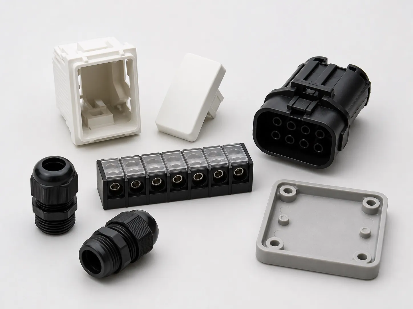
There is a compliance reason too. The Electrical Accessories (Quality Control) Order, 2023 made the BIS Standard Mark compulsory for items such as boxes and enclosures to IS 14772, bayonet lamp holders to IS 1258 and switch-socket-outlets to IS 15787. Where such parts carry moulded-in metal, a consistent insert position feeds straight into a consistent, certifiable product.
What should you send to size your insert moulding job?
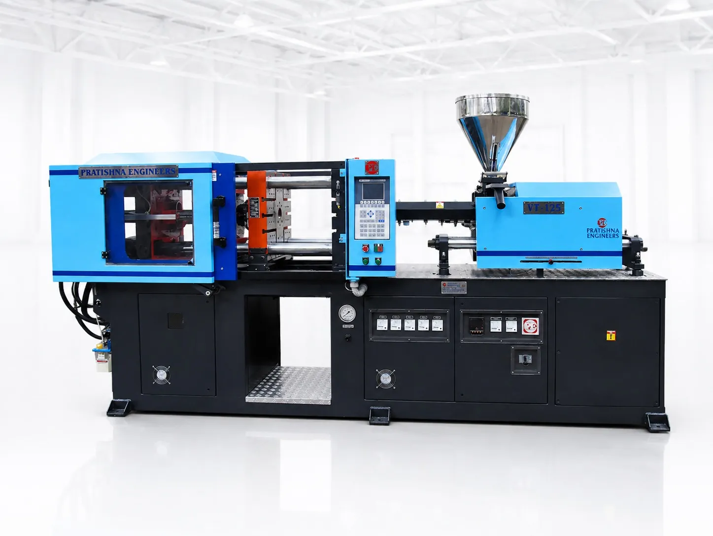
Send the part drawing, the insert drawing and the number of inserts per part, the resin grade, the cavity count you want, and a timed loading trial if you have one. With those, clamp force, shot size and table type can be worked out together. See the vertical clamp insert moulding machines page for the range this job would be matched against.
Frequently Asked Questions About Insert Moulding Setup
Can a horizontal machine do insert moulding?
Yes, but each insert has to be held on a vertical mould face by a magnet, spring clip, vacuum or tight press fit, which suits robot loading. For small parts with several loose inserts loaded by hand, a vertical clamp is easier because gravity keeps each insert seated in the upward-facing lower half.
Should brass inserts be preheated before loading?
Preheating is worth a trial on most jobs. Design guidance from DuPont lists lower post-mould shrinkage stress, pre-expansion of the insert and better weld lines as the benefits. Keep the heating time and temperature steady from shot to shot, because a cold insert in one cavity behaves differently from a hot one next to it.
How do I stop inserts tilting in the mould?
Give each insert one locating feature with a close fit, a stop face that sets its height, and enough engagement on the pin to resist the melt front. Check incoming insert dimensions, keep pockets free of debris, and position the gate so the melt does not strike the insert side-on at high speed.
Do inserts change the clamp force a mould needs?
Not much. Clamp force still follows the projected area of the cavities and cold runner times a tonnage factor for the resin. An insert that passes right through the part can reduce the moulded area slightly, while an insert inside the cavity outline leaves it unchanged, so size the clamp on the full part area.
How many inserts can one operator load per cycle?
There is no fixed number. Time the placement of one insert, multiply by the inserts per shot, and add part removal and inspection. If that open-mould time reaches the clamp-closed time, the operator is the bottleneck, and a sliding second lower half or automated feeding becomes worth costing.
Related Articles
- Moulding Plug Tops With Brass Pins on a Vertical Machine
- Sliding Moulds on Vertical Machines: How Much Cycle Time They Save
- Threaded Brass Inserts in Plastic Parts: Moulding and Pull-Out Strength
Sources & References
- PlasticsToday (IMM), summarising A. Miller, DuPont: Design and material advice from the pros, Part 3: Insert molding essentials (Sept 2005)
- aPriori: Cost Model Guide: Insert Injection Molding Options
- Robotic Industries Association via Smart Molding, J. Clark: Automated injection molding operation
- Gazette of India (DPIIT): Electrical Accessories (Quality Control) Order, 2023
Technical Disclaimer
Disclaimer: The information provided in this document is for general informational and educational purposes only. It is based on technical references and industry information available at the time of preparation and may be subject to change. It does not constitute engineering, technical, commercial or professional advice, nor does it constitute a quotation, specification, warranty or contractual commitment by Pratishna Engineers.
Actual injection moulding machine and process requirements vary according to the component design, material, mould, production volume, machine configuration and operating conditions. The information, examples, calculations and recommendations provided should be independently evaluated and verified for the specific application before making any equipment, process or production decision. Information obtained from third-party sources remains subject to the accuracy and limitations of those sources.
Limitation of Liability: Pratishna Engineers makes no representation or warranty, express or implied, regarding the completeness, accuracy or suitability of the information for any particular application. To the extent permitted by applicable law, Pratishna Engineers shall not be liable for any loss, damage, cost or consequence arising from reliance on or use of the information contained in this document. Final machine selection, configuration and application suitability should be confirmed with Pratishna Engineers based on complete and accurate project requirements.