
A strain relief with a 4.5 mm wall needs about 2.25 times the cooling of one with a 3 mm wall, because cooling time rises with the square of thickness. At 6 mm it needs four times. That single ratio decides most of the strain relief moulding work for heavy cords on a 55 t machine.
Heavy cords bring thicker jackets, longer tails and harder pull and torque tests. At 55 t the clamp is seldom what runs out for reliefs. Cooling time, the grip on the jacket and loading time do, and the sections below take them in turn.
Key Takeaways
- Cooling time follows the square of the thickest wall, so coring out a thick tail saves more cycle time than any machine setting.
- IEC 60884-1 includes a cord anchorage test of 100 pulls of 60 N, one per second, followed by a torque test.
- Grip on the jacket comes from bond, length of contact and shape, so the mould has to seal tightly at the cord exit without crushing it.
- With a long cooling time, cavity count is set by the hourly target; clamp is checked last.
What Makes Strain Relief Moulding for Heavy Cords Different?
Everything is bigger except the time available. A heavy cord has a thicker jacket and stiffer conductors, so the relief is longer and thicker to spread the bend. Thicker sections take longer to cool, need more shot and must be fully packed to avoid voids near the cord.
The relief does two jobs. It anchors the cord so that a pull or twist reaches the moulding, not the terminations. It also spreads bending over a tapered length, so the cord does not kink where it leaves the housing or plug.
Both jobs push the design toward a long tapered tail with a thick root. That root is where cooling time, sink and voids concentrate, and where the mould grips the jacket. Good tails taper evenly and can use ribs or segments, which flex well and cool faster than a solid cone.
Gate position matters more on a long tail. Gating into the thick root lets hold pressure pack the section that shrinks most, and the melt fills toward the thin tip, where the vent belongs. Gating at the tip does the opposite: the thin end freezes first and leaves the root unpacked.
How Do Pull and Torque Tests Shape the Design?
They set how much grip the moulding must have on the jacket. In IEC 60884-1, the international standard for plugs and sockets, the cord anchorage test applies 100 pulls of 60 N at one per second, then a torque test, as cord supplier Interpower describes it.
Cord tests and what they ask of a moulded strain relief
| Test or load | What can fail | What helps at the mould and machine |
|---|---|---|
| Repeated pulls on the cord | Cord slides in the relief; terminations take the load | Bonding compound matched to the jacket, enough contact length, full pack at the root |
| Torque on the cord | Cord twists inside the relief | Bond to the jacket; a non-round section or ribs inside the grip zone |
| Repeated bending at the exit | Jacket cracks where the relief ends | Even taper to a thin, flexible tip; no flash ring at the exit |
| Impact or crushing in use | Voids or weld lines crack | Liberal gating, venting at the last fill point, no overheated compound |
The cord under the relief is a regulated product in its own right. BIS lists PVC cables to IS 694 under compulsory ISI certification, so the jacket grade is fixed by the cable maker. Match the relief compound to that jacket, and ask the cable supplier before changing either one.
A flash ring at the cord exit deserves special attention. It forms a hard edge where the cord bends most, which can cut the jacket during repeated bending. Size the exit shut-off to the cord's thinnest reel, not its average.
The jacket surface also affects the grip. Dust, talc or release agent left from cable extrusion can stop the melt fusing with the jacket, so keep cords clean and dry in the loading area and treat them as part of the moulding process, not as loose stock.
How Long Does a Thick Strain Relief Take to Cool?
Longer than most of the rest of the cycle put together. RJG's guidance says wall thickness is squared in the cooling equation, so the thickest section sets the time. In one RJG trial on a 3.3 mm part, about 85% of the cycle was cooling.
The same guidance notes that only about 40% of the heat must be removed for the part to be ejected, and suggests adding about 20% to the calculated cooling time as a safety factor. For soft PVC, ejecting too early lets the tail sag or mark, so trial the timer on real cords.
Our view: core out a thick root before you buy cycle time with more cavities. Replacing a solid 6 mm section with ribs of about 3 mm cuts that section's cooling to roughly a quarter, and the strain relief often flexes better too.
If the heavy cord calls for a harder flexible PVC, expect a hotter melt. The Teknor Apex guide moves from about 163 °C for Shore A50 to 60 up to about 199 °C for Shore C80 to 90. More heat to remove is one more reason to keep sections thin and even.
A tail that is still warm at ejection can be handled safely if it is laid straight to finish cooling. A simple rack beside the machine stops reliefs from setting in a bent shape, which a later bend test would expose.
How Many Cavities Does a Strain Relief Cell Need?
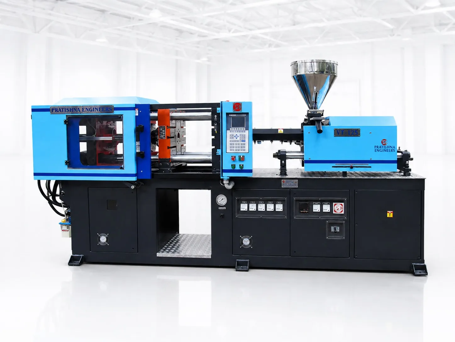
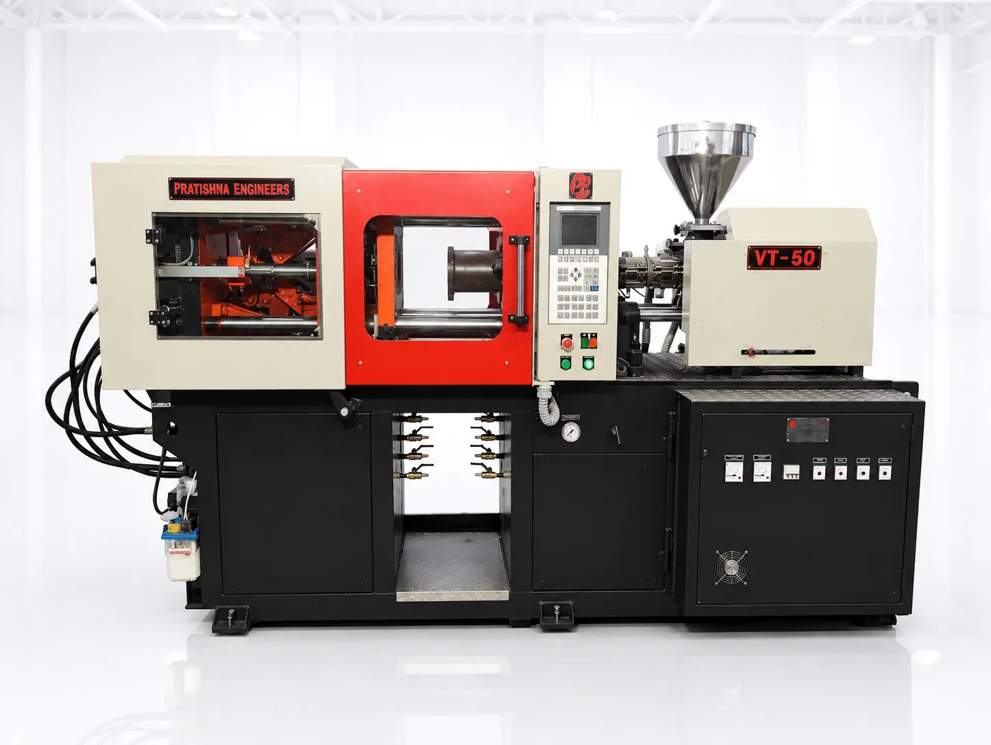
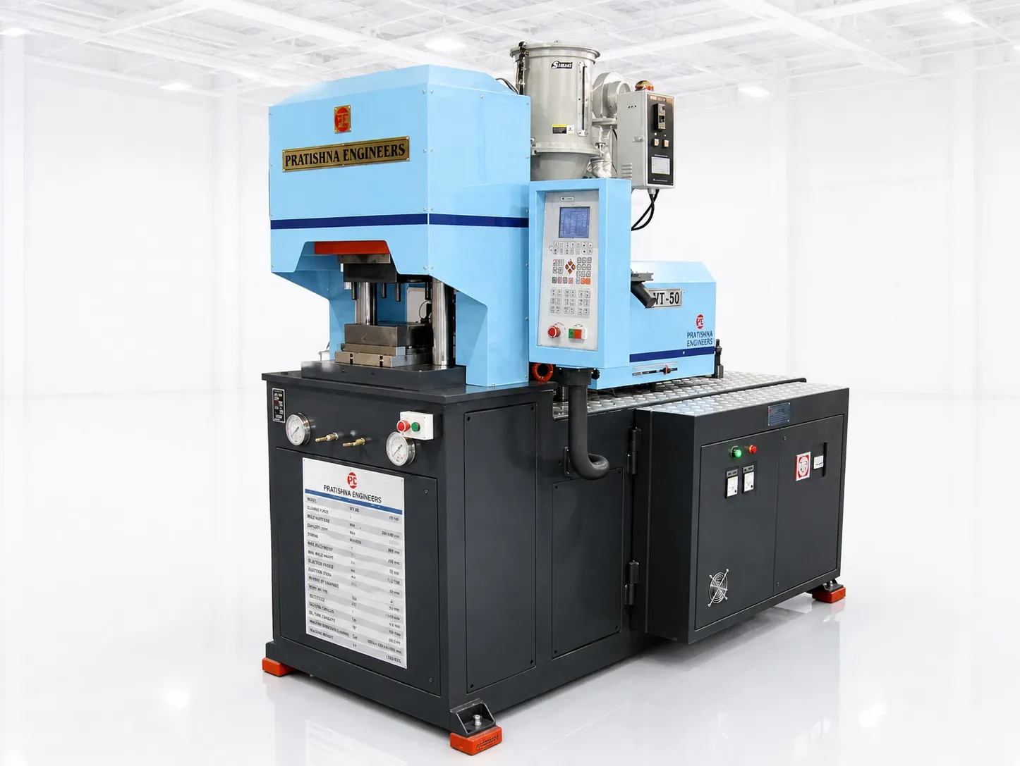
Start from the hourly target and the cycle, which here is mostly cooling, then add a cavity at a time and include the extra loading each one brings. Check the clamp last. Thick reliefs fit a 55 t clamp in several cavities, so cooling and loading usually set the count. See the 55 ton vertical injection moulding machine page.
Frequently Asked Questions About Strain Relief Moulding
Should a heavy cord strain relief be solid or ribbed?
Ribbed or segmented, where the design allows. Ribs of even thickness cool faster than a solid cone, show less sink and let the tail flex progressively. Keep a solid band at the root where the relief grips the jacket, and taper the ribs toward the tip so the cord does not bend at one point.
Why does the cord pull out of the relief during testing?
The bond or the grip length is too small. Check that the relief compound bonds to the jacket material, that the root was fully packed, and that the contact length is long enough. Melt that is too cold at the cord can also stop the two surfaces fusing, so check melt temperature at the nozzle.
Can a strain relief be moulded in two shots?
Yes. A first shot can form a stiffer inner sleeve or anchor around the cord, and a second, softer shot forms the flexible tail. Each shot is thinner, so each cools faster, and the inner shot holds the cord centred while the outer one fills.
Does mould temperature matter for flexible PVC reliefs?
Yes. A colder mould shortens cooling, but too cold a surface can leave flow marks and weaken the bond at the jacket. Flexible PVC processing guides give a mould range of roughly 10 to 43 °C. Set it evenly on both halves so the tail does not bow on ejection.
How do I stop sink marks on the thick root?
Pack the root fully while the gate is still open, which needs a gate large enough not to freeze early. Gate into the thickest section where you can. If sink remains, the section is too thick: core it out or add ribs rather than raising hold pressure, which can flash the cord exit.
Related Articles
- What Can You Make on a 55 Ton Vertical Moulding Machine?
- Two-Cavity Cable Moulds on a Horizontal Clamp Vertical Machine
- Wire Harness Parts: Overmoulding Clips and Grommets
Sources & References
- Interpower: Cord Anchorage Pull Test (IEC 60884-1, Section 23)
- RJG Inc.: How to Determine Injection Molding Cooling Time
- Bureau of Indian Standards: Scheme I (ISI Mark Scheme): products under compulsory certification
- Teknor Apex: Processing Guide for Injection Molding of Apex Flexible PVC Compounds
Technical Disclaimer
Disclaimer: The information provided in this document is for general informational and educational purposes only. It is based on technical references and industry information available at the time of preparation and may be subject to change. It does not constitute engineering, technical, commercial or professional advice, nor does it constitute a quotation, specification, warranty or contractual commitment by Pratishna Engineers.
Actual injection moulding machine and process requirements vary according to the component design, material, mould, production volume, machine configuration and operating conditions. The information, examples, calculations and recommendations provided should be independently evaluated and verified for the specific application before making any equipment, process or production decision. Information obtained from third-party sources remains subject to the accuracy and limitations of those sources.
Limitation of Liability: Pratishna Engineers makes no representation or warranty, express or implied, regarding the completeness, accuracy or suitability of the information for any particular application. To the extent permitted by applicable law, Pratishna Engineers shall not be liable for any loss, damage, cost or consequence arising from reliance on or use of the information contained in this document. Final machine selection, configuration and application suitability should be confirmed with Pratishna Engineers based on complete and accurate project requirements.