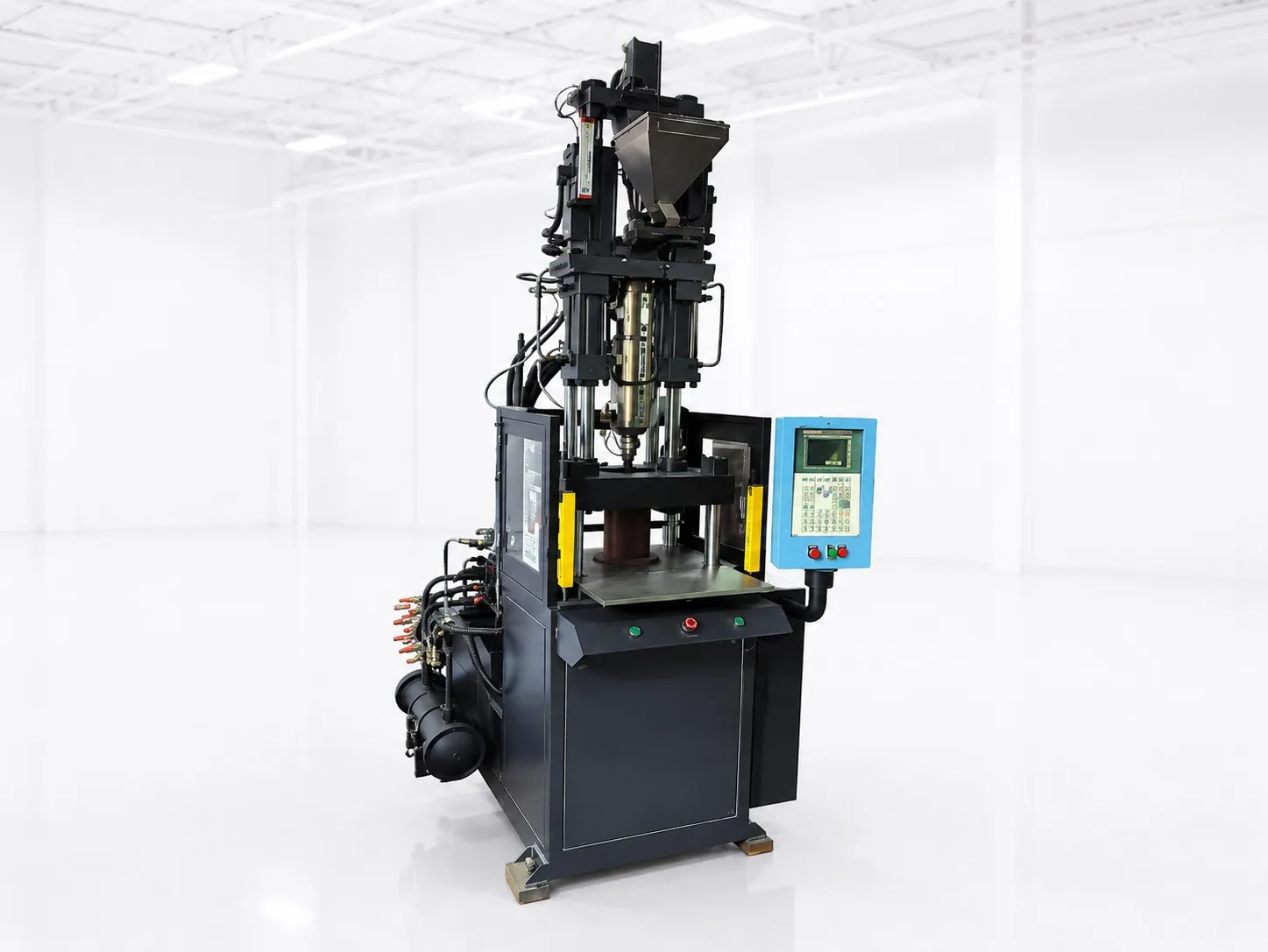

A new 8-cavity lid mould arrives, the first shots look good, and a week later two cavities are blocked off because they flash or fall short. Output drops to six parts a shot and the payback stretches. Getting the most from a multi-cavity mould on a 75 to 180 t machine comes down to three things: a clamp sized for every cavity plus the runner, flow that reaches each cavity at the same time, and a cycle set by cooling.
Get those right and each extra cavity adds parts for little extra cycle time. Get them wrong and the extra cavities add scrap, sorting and downtime instead.
Key Takeaways
- Every cavity and the cold runner add projected area, so clamp grows almost in step with cavity count. A hot runner takes the runner out of the sum.
- Cooling can take up most of the cycle. RJG measured about 85% of one 8-cavity ABS cycle as cooling, so wall thickness is a bigger lever than cavity count.
- Output per hour is 3,600 ÷ cycle × cavities × good-shot share. A cavity blocked off for a month cuts output in direct proportion.
- For drip emitters, IS 13487:2024 sets uniformity categories A and B, which makes cavity-to-cavity consistency a product requirement.
How Many Cavities Can Your Clamp Carry?
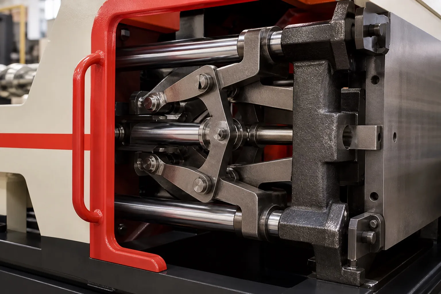
Multiply one cavity's projected area by the cavity count, add the cold runner, and multiply by the resin's tonnage factor with a reserve. The largest count that stays under the rated clamp is your ceiling. The tonnage selection article in this series sets out the full method.
The runner is where multi-cavity tools differ. A long cold runner feeding eight cavities adds area that a single-cavity tool never carries. The method in Williams' Plastics Technology column counts the full cold-runner area, while with a hot runner only the cavities count.
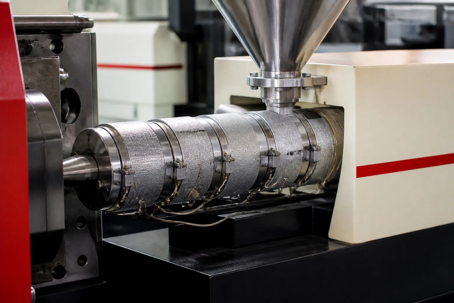
Shot grows in step with the cavities. Eight cavities plus a runner can push a small screw close to the top of its working range, so check shot volume at the same time as clamp, not after the mould is cut.
Mould size is the third limit. More cavities mean a wider, taller mould, and it must still pass between the tie bars and sit on the platen. A layout that suits the clamp can still fail on mould width.
Why Do Some Cavities Fill Before Others?
Cavities fill unevenly when melt reaches them by paths of different length, temperature or resistance. Near cavities pack while far ones are still filling, so one shot can hold flashed parts and short parts together. Runner layout and gate sizing are the first places to look.
A naturally balanced runner gives every cavity the same flow length and the same number of turns. Layouts in a straight line, often chosen to save mould width, are not naturally balanced, and their gates may need sizing to compensate.
A short-shot study shows the pattern quickly. Fill at a reduced shot size, number the cavities and weigh each part. If the far cavities are light shot after shot, the problem is flow balance, not the machine.
For some Indian products, balance is a rule, not a preference. The BIS compendium on micro-irrigation lists IS 13487:2024 for emitters, with uniformity categories A and B. Emitters from every cavity go into the same field, so a cavity that runs differently can show up as uneven flow along the line.
Our view: a balanced 4-cavity mould that runs every cavity is worth more than an 8-cavity mould that runs with two blocked. Pay for balance at the design stage, when it costs a drawing change rather than weeks of trials.
Does Doubling Cavities Double Your Multi-Cavity Mould Output?
Not quite. Doubling cavities doubles parts per shot, but the cycle can lengthen with a bigger shot, a longer runner and more ejection travel. Output comes close to twofold only when every cavity runs, cooling reaches each one equally and the clamp holds without flash.
RJG notes that cooling time depends most on wall thickness, which is squared in the cooling equation. In its trial on an 8-cavity ABS tensile-bar mould with a 3.3 mm wall, about 85% of the cycle went on cooling.
That makes wall thickness a bigger lever than cavity count. A wall 20% thinner needs about 36% less cooling time, because 0.8² is 0.64.
Cooling also has to reach every cavity equally, or the slowest cavity sets the cycle for all of them. RJG adds that only about 40% of the heat must be removed before ejection, and suggests adding about 20% to the calculated cooling time as a safety factor.
During the first trials, log mould surface temperature at an inner and an outer cavity. A steady gap between them points to the cooling layout, not to the process settings.
Hourly output from a lid mould, using assumed cycles for illustration and a 98% good-shot share
| Set-up | Cycle (assumed) | Cavities running | Parts per hour |
|---|---|---|---|
| 4 cavities, cold runner | 12 s | 4 | 3,600 ÷ 12 × 4 × 0.98 = 1,176 |
| 8 cavities, hot runner, all running | 13 s | 8 | 3,600 ÷ 13 × 8 × 0.98 = 2,171 |
| 8 cavities, hot runner, 2 blocked | 13 s | 6 | 3,600 ÷ 13 × 6 × 0.98 = 1,628 |
What Should You Check Before Ordering a Multi-Cavity Mould?
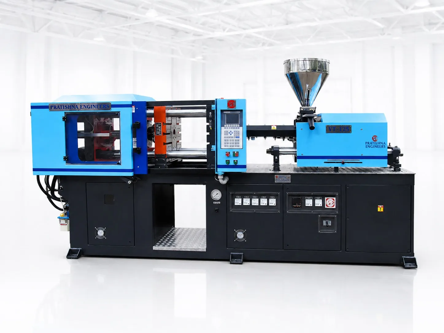
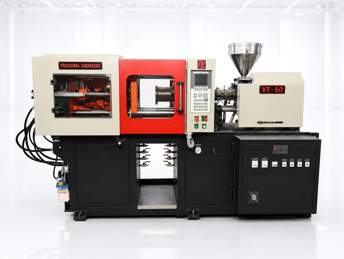
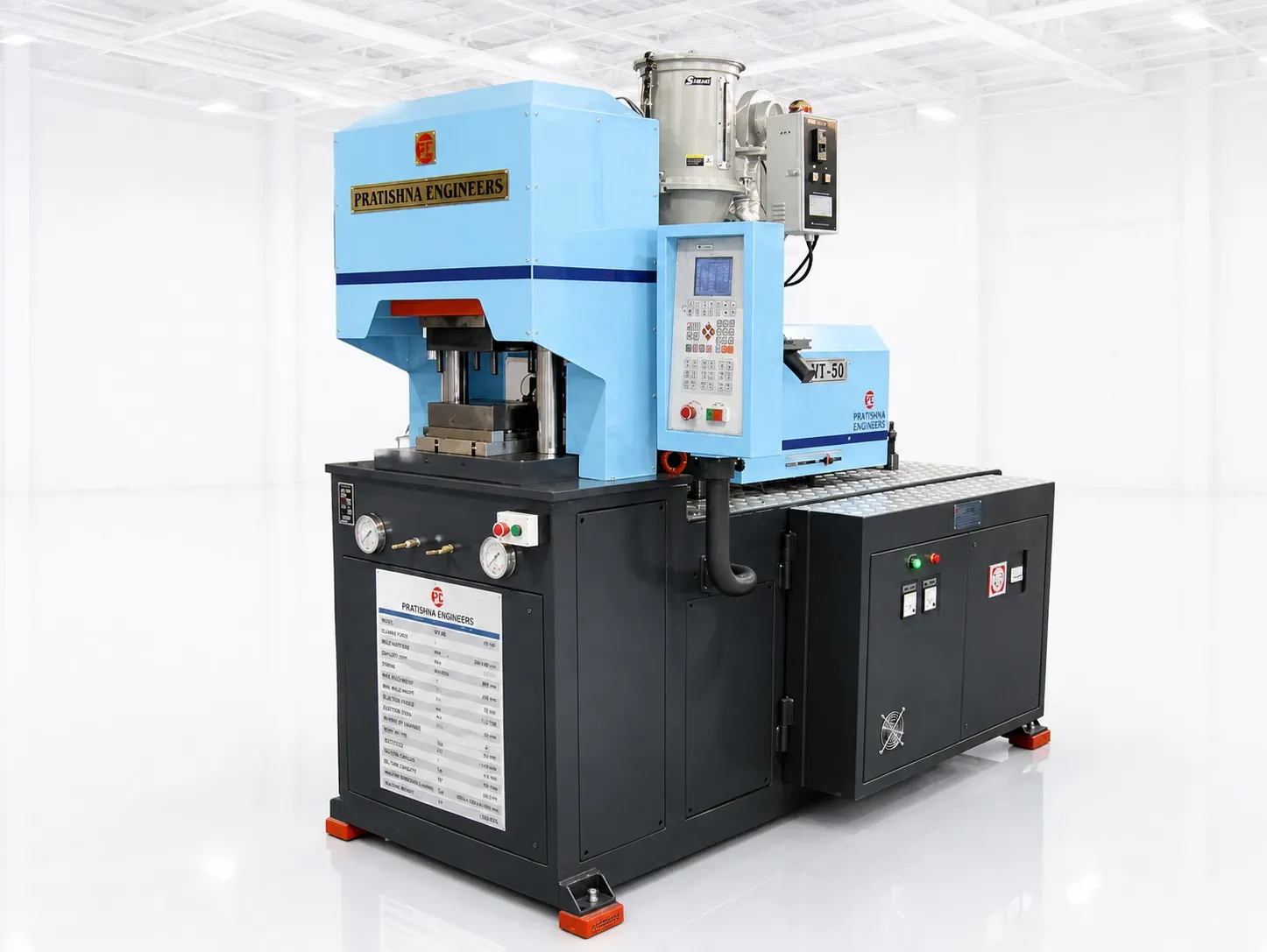
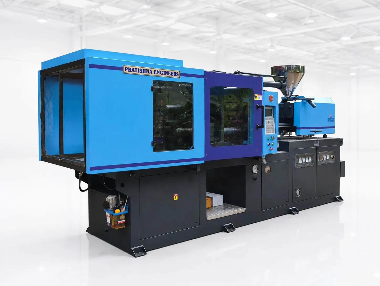
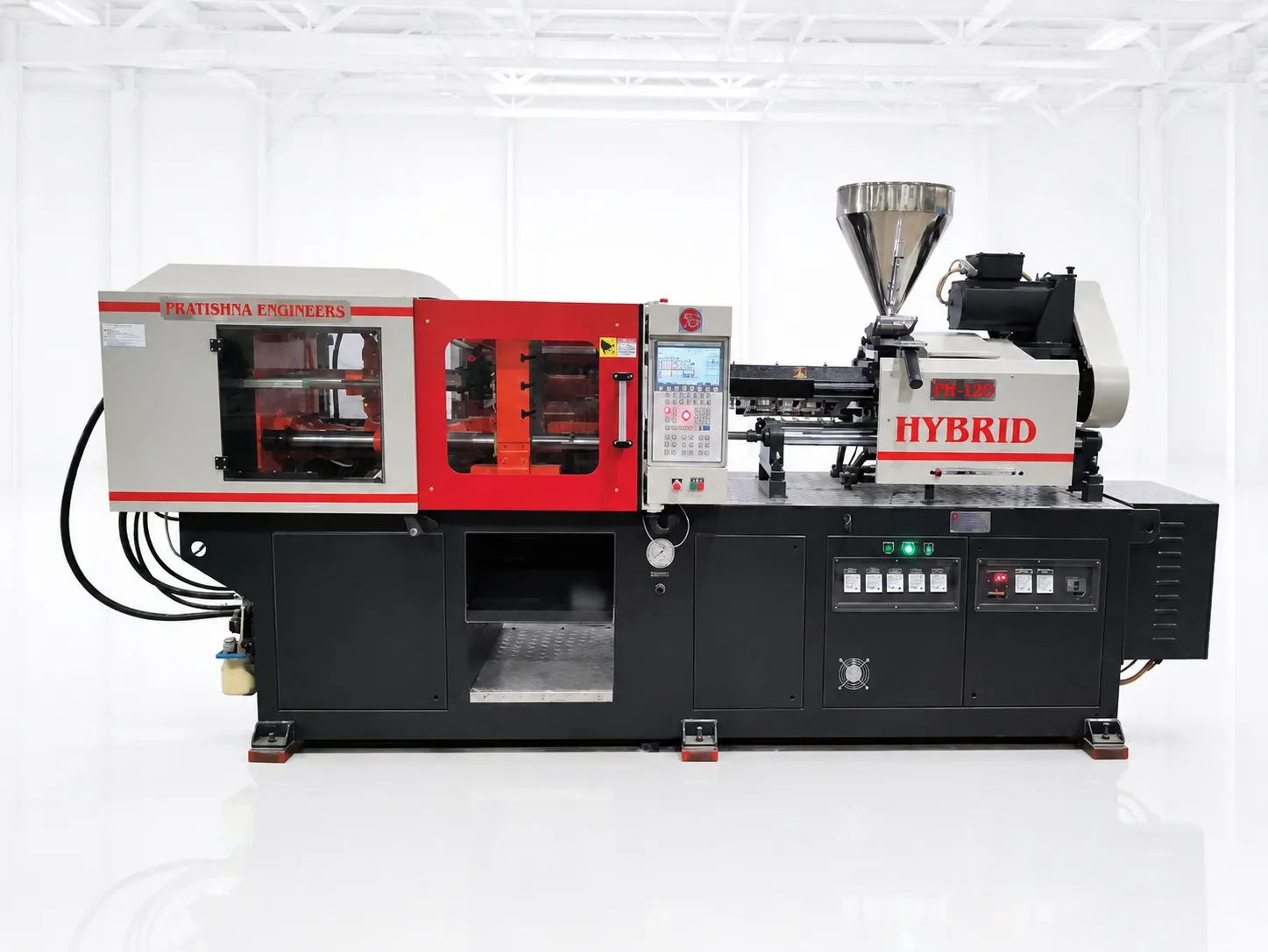
Fix the cavity count against clamp, shot, mould size and runner type together, and ask the toolmaker for the runner and cooling layouts. Send those with the part drawing and resin, and the machine can be matched to the mould before steel is cut. See the 75 to 180 ton horizontal injection moulding machine page.
Frequently Asked Questions About Multi-Cavity Moulds
What is a balanced runner?
A balanced runner gives every cavity the same flow length, the same number of bends and the same runner sizes from the sprue to the gate. Melt then reaches each cavity at about the same time and pressure. Moulds laid out in a line can be balanced artificially by sizing runners or gates differently.
Should I block off a cavity that keeps giving short shots?
Only as a short-term measure. Blocking a cavity shifts flow and pressure to the others, which can change their weight and dimensions, so re-check every remaining cavity. Plan a proper fix, such as gate or runner correction, venting or cooling repair, before the blocked cavity becomes permanent.
Is a hot runner worth it on a multi-cavity mould?
It can be. A hot runner removes cold-runner scrap and runner area from the clamp sum, and can shorten the cycle where the runner is the thickest section. It costs more and needs temperature control and maintenance, so compare its price with your resin savings and output gain over the mould's life.
How do I work out hourly output from a multi-cavity mould?
Divide 3,600 by the cycle time in seconds, multiply by the number of cavities that are actually running, then by the share of good shots. A 10 s cycle with 6 running cavities and 97% good shots gives 3,600 ÷ 10 × 6 × 0.97, or about 2,095 parts an hour.
Does a multi-cavity mould need a larger screw?
Often it needs a larger shot, so check it. Add the weight of every cavity and the cold runner, convert to melt volume and add about 10% before comparing with the screw's swept volume. If the total sits above about 65% of capacity, the larger screw option or a hot runner may be needed.
Related Articles
- Injection Moulding Machine Tonnage Selection: Matching 75 to 180 Tons to Your Part
- Screw Diameter Choice: Shot Weight vs Injection Pressure on 75 to 180 Ton Machines
- Injection Moulding Machine Upgrade: When to Move to a Container or Houseware Machine
Sources & References
- Plastics Technology, J. Williams (RJG): Clamp Tonnage: More Is Better...Right?
- Plastics Engineering (SPE), A. Urbina: Mastering Clamping Force Calculation
- RJG Inc.: How to Determine Injection Molding Cooling Time
- Bureau of Indian Standards: Compendium of Indian Standards: Micro-Irrigation Systems
Technical Disclaimer
Disclaimer: The information provided in this document is for general informational and educational purposes only. It is based on technical references and industry information available at the time of preparation and may be subject to change. It does not constitute engineering, technical, commercial or professional advice, nor does it constitute a quotation, specification, warranty or contractual commitment by Pratishna Engineers.
Actual injection moulding machine and process requirements vary according to the component design, material, mould, production volume, machine configuration and operating conditions. The information, examples, calculations and recommendations provided should be independently evaluated and verified for the specific application before making any equipment, process or production decision. Information obtained from third-party sources remains subject to the accuracy and limitations of those sources.
Limitation of Liability: Pratishna Engineers makes no representation or warranty, express or implied, regarding the completeness, accuracy or suitability of the information for any particular application. To the extent permitted by applicable law, Pratishna Engineers shall not be liable for any loss, damage, cost or consequence arising from reliance on or use of the information contained in this document. Final machine selection, configuration and application suitability should be confirmed with Pratishna Engineers based on complete and accurate project requirements.