



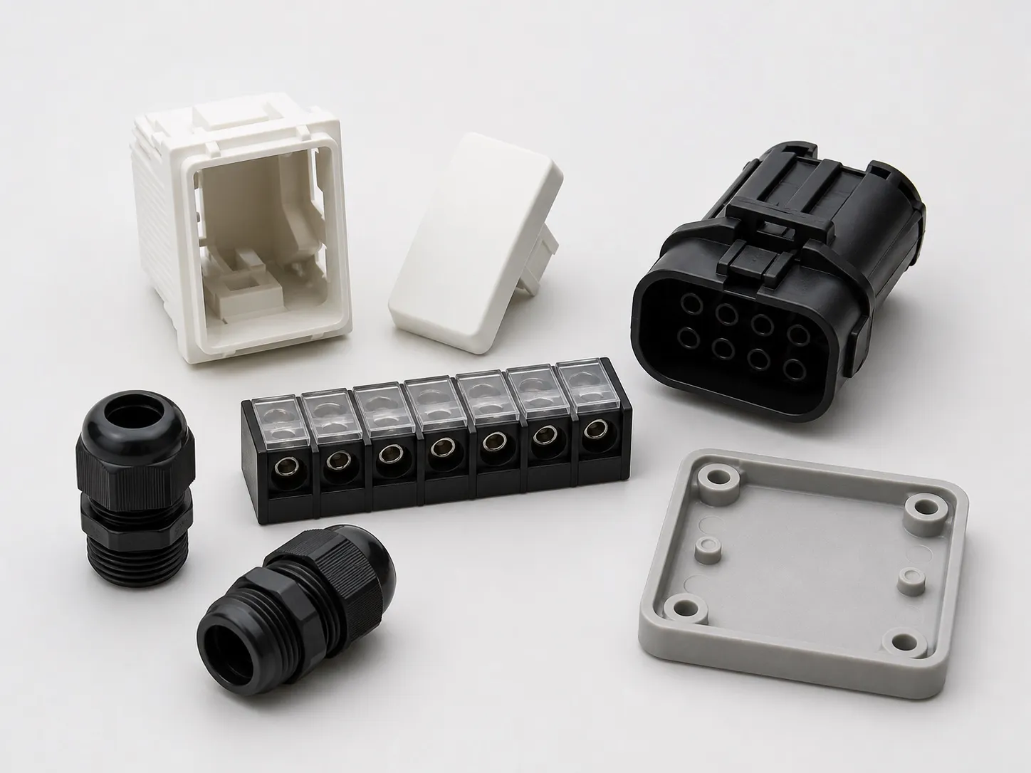

Four cavities of a 45 × 20 mm connector body, plus a 4 cm² runner, project 40 cm². At 3 to 5 US t/in² with a 10% reserve (a starting margin, not a rule), the mould needs about 19 to 31 t, roughly a third to a half of a 60 t clamp. In connector insert moulding, that gap matters: clamping at full tonnage does not cure flash, and it can cause damage.
Flash on a connector can come from terminals that sit badly, shut-offs that do not seal and vents cut or worn to the wrong depth. This article covers each, then the tests the moulded body faces.
Key Takeaways
- A four-cavity connector mould can need only a third to a half of a 60 t clamp; set clamp to the mould, not the machine maximum.
- Over-clamping is linked to crushed vents, broken inserts, burns, short shots and cracked mould blocks.
- Vent depth has no single number; tune it in small steps until whisker flash appears, then back off.
- Connector bodies may face glow-wire tests, and switch-socket-outlets now need the BIS Standard Mark under a 2024 order.
How Are Terminals Located in Connector Insert Moulding?
By pockets in the lower mould that fix each terminal's position and depth, with steel faces that seal around the contact area. On a vertical machine the terminals stand in their pockets under gravity. The pocket sets location; the seal around it decides whether the contact face stays clean.
Locate each terminal from a datum that also locates the connector body, so terminal position and body outline come from one reference. If the terminal sits on one steel and the body is formed by another, tolerances stack and terminal position drifts across cavities.
Terminals still joined on their stamped strip hold their own pitch and load as a set, which helps on long rows. Loose terminals give more freedom in layout but put each one's position in the operator's hands.
Melt pressure is the other load on a terminal. A long, thin blade can bend as melt flows past it, so support it close to where the plastic will grip it, and gate so flow reaches the row from the side rather than head on.
Where Does Flash on a Connector Come From?
From any gap the melt can enter: around a terminal that does not seal, at a worn shut-off, at a vent cut too deep, or across the parting line when clamp is too low. Each leaves its own signature, so read where the flash sits before changing the process.
Where connector flash appears and what it can point to
| Where the flash sits | Likely cause | First check |
|---|---|---|
| On a terminal contact face | Terminal not sealing in its pocket; pocket worn | Terminal dimensions against the pocket; pocket wear |
| Along the parting line, all round | Clamp too low, or injection or hold pressure too high | Clamp setting against calculated need; transfer and hold |
| At one vent | Vent cut or worn too deep | Vent depth against the tuned value |
| In one cavity only | Imbalanced fill overpacking that cavity | Short-shot weights cavity by cavity |
| Burns or short shots near terminals | Vents too shallow or coined shut | Vent depth on both mould halves |
Raising clamp is the tempting fix, and it can be the wrong one. Writing in Plastics Technology, RJG's Jeremy Williams lists over-clamping effects that include burns, short shots, crushed vents, a rolled parting line, broken inserts and cracked mould blocks. On an insert mould, a broken terminal pocket is an expensive repair.
Cavity-to-cavity flash can come from fill imbalance. A Plastics Technology article on multi-cavity balance describes turning off hold pressure so every part is slightly short, then weighing them, to see which cavity fills first.
How Deep Should Connector Vents Be?
There is no fixed number. A MoldMaking Technology article by Steven Shannon says resin suppliers give a range, about 0.013 to 0.051 mm in its PP example, and that moldmakers cut at the shallow end to avoid flash. The moulder then tunes each vent on a trial set.
The method is to deepen a vent by about 0.005 to 0.008 mm per step, cycling after each, until whisker flash appears, then back off about 0.005 mm. Burn marks disappearing is another sign the vent is working. Secondary vents run about 0.64 to 0.76 mm deeper, behind a 1.5 to 2.0 mm land.
The same article warns that repeated clamping can coin vents shut, so check them on both mould halves at every maintenance stop. Vents, lands and secondary vents should be identical cavity to cavity, or each cavity will fill and pack differently.
Which Fire Tests and Indian Rules Apply?
Connector and accessory bodies can face glow-wire tests. IEC 60695-2-12:2021 defines the glow-wire flammability index as the highest test temperature at which the material does not ignite, or extinguishes within 30 s, without igniting the tissue below. It is a materials test used for preselection.
In India, the Electrical Accessories (Quality Control) Order, 2023, S.O. 43(E), made the BIS Standard Mark compulsory for switch-socket-outlets to IS 15787:2008, along with bayonet lamp holders, boxes and enclosures, and cable trunking. Small and micro enterprises got nine and twelve months to comply.
Our view: fix the connector grade and its glow-wire data before cutting steel, and never change grade, colour or regrind share without the customer's sign-off. A cheaper grade that moulds well can still fail the fire test the product needs.
What Should You Bring to a Connector Mould Trial?
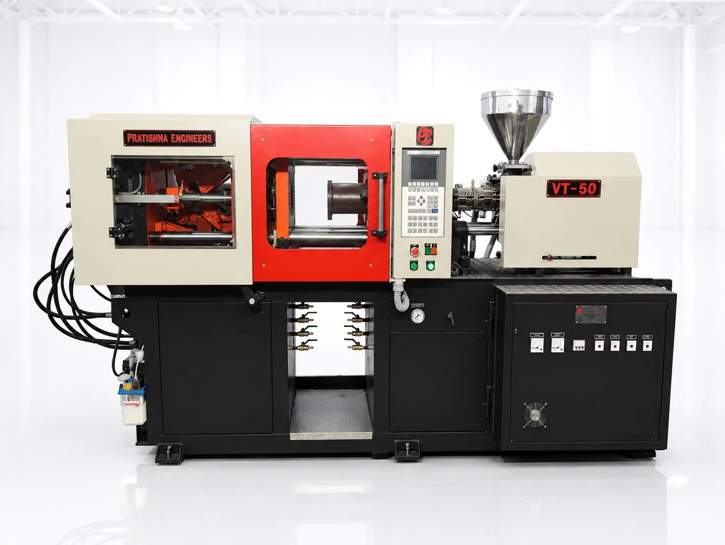
Bring terminal drawings and samples from more than one batch, the body drawing with contact faces marked, the resin grade with its fire-test data, and the target cavities and output. Plan vent tuning time into the trial. See the 60 ton vertical injection moulding machine page.
Frequently Asked Questions About Connector Insert Moulding
Why do terminals bend during moulding?
Melt flowing past a long, thin blade pushes it sideways, especially when the gate aims flow straight at the row or fill speed is high. Support the terminal close to where the plastic grips it, gate so flow arrives from the side, and slow the fill as the melt reaches the terminals.
Should I raise clamp force to stop connector flash?
Only after you have checked clamp against the calculated need. If the mould already has enough clamp, more force will not seal a worn pocket or a deep vent, and it can crush vents and break inserts. Find where the flash sits first, then fix that cause.
How often should vents on an insert mould be checked?
At every planned maintenance stop and whenever burns, short shots or flash appear. Repeated clamping can coin vents shut, and deposits from additives can build up. Measure both mould halves and record the depths, so changes over time are visible and every cavity stays matched.
Can a connector mould run without vents on the terminal side?
Air still has to leave the cavity, and terminals block some of its paths. Without vents near the last places to fill, trapped air can burn the plastic or leave short shots behind the terminals. Vent ejector pins and parting lines near those points where the design allows.
Do PBT and nylon connectors need different settings?
Yes. They differ in melt temperature, drying needs, shrinkage and how quickly they set up, so each grade needs its own settings from the supplier's datasheet. Nylon is hygroscopic and must be dried to the supplier's moisture limit. Never carry one grade's settings over to the other.
Related Articles
- What Can You Make on a 60 Ton Vertical Insert Moulding Machine?
- Plug Tops With Brass Pins on a 60 Ton Vertical Machine
- Threaded Bush Inserts: Getting Pull-Out Strength Right
Sources & References
- MoldMaking Technology, S. Shannon (The Estee Lauder Companies): How to Determine the Proper Vent Depth (2019, updated 2024)
- Plastics Technology, J. Williams (RJG): Clamp Tonnage: More Is Better...Right?
- IEC Webstore: IEC 60695-2-12:2021
- Gazette of India (DPIIT): Electrical Accessories (Quality Control) Order, 2023, S.O. 43(E)
Technical Disclaimer
Disclaimer: The information provided in this document is for general informational and educational purposes only. It is based on technical references and industry information available at the time of preparation and may be subject to change. It does not constitute engineering, technical, commercial or professional advice, nor does it constitute a quotation, specification, warranty or contractual commitment by Pratishna Engineers.
Actual injection moulding machine and process requirements vary according to the component design, material, mould, production volume, machine configuration and operating conditions. The information, examples, calculations and recommendations provided should be independently evaluated and verified for the specific application before making any equipment, process or production decision. Information obtained from third-party sources remains subject to the accuracy and limitations of those sources.
Limitation of Liability: Pratishna Engineers makes no representation or warranty, express or implied, regarding the completeness, accuracy or suitability of the information for any particular application. To the extent permitted by applicable law, Pratishna Engineers shall not be liable for any loss, damage, cost or consequence arising from reliance on or use of the information contained in this document. Final machine selection, configuration and application suitability should be confirmed with Pratishna Engineers based on complete and accurate project requirements.