
Going from 165 t to 180 t adds 15 t, about 9% more clamp. At a tonnage factor of 3 US t/in² and a 10% reserve (a starting margin, not a rule), the largest projected area rises from about 356 cm² to about 388 cm². That is a gain of roughly 32 cm², a square only 5.7 cm a side.
So in a 165 ton vs 180 ton injection moulding machine decision, the extra clamp may not settle it alone. The deciding numbers can be the frame's: tie-bar space, platen size, mould height and stroke. If your mould does not pass between the tie bars, the extra tonnes do not help at all.
Key Takeaways
- 180 t gives about 9% more clamp than 165 t, worth roughly 20 to 50 cm² of extra projected area at tonnage factors of 2 to 5.
- The mould must pass between the tie bars, and at the least the cavities should sit inside them, because platens can pull in near the tie bars.
- A bigger frame raises the minimum mould size too. A Plastics Technology setting guide asks for the mould to cover at least 70% of the distance between the tie bars.
- Compare shut height, stroke, daylight, locating ring and mounting pattern on both datasheets before you choose on tonnage.
What Changes Between a 165 Ton vs 180 Ton Injection Moulding Machine?
The clamp rises by about 9%, and on adjacent sizes the frame can change too: tie-bar space, platen size and sometimes stroke and mould height. The injection unit may be the same. Read both datasheets side by side, because the frame figures decide which moulds fit.
Largest projected area at 165 t and 180 t, with a 10% reserve
| Tonnage factor (US t/in²) | 165 t | 180 t | Gain |
|---|---|---|---|
| 2 | 533 cm² | 582 cm² | 49 cm² |
| 3 | 356 cm² | 388 cm² | 32 cm² |
| 4 | 267 cm² | 291 cm² | 24 cm² |
| 5 | 213 cm² | 233 cm² | 20 cm² |
The table follows the clamp method explained in the applications article in this series. The gain is real but modest. A part that sits just above the 165 t limit at its tonnage factor may fit 180 t; a part that needs 200 t will not fit either.
Our view is clear: buy the 180 t only when the clamp calculation or the mould's size needs it. A bigger frame on a small mould costs more to buy and run, and it can harm the mould, as the next sections show.
Why Does Tie-Bar Space Decide Which Moulds Fit?
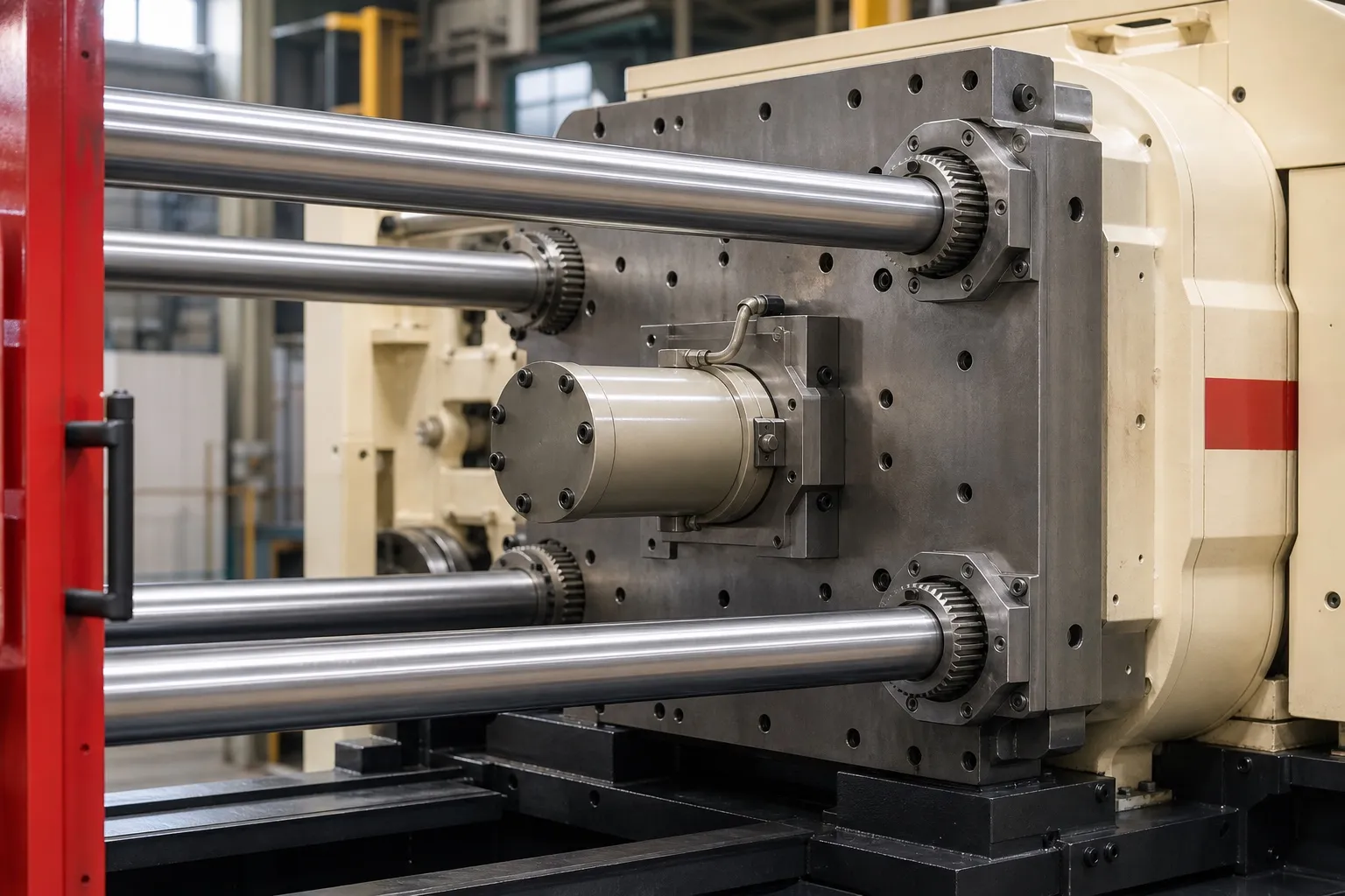
Tie-bar space is the clear gap between the bars, horizontal by vertical. The mould has to pass through it when it is loaded, and the parts have to sit inside it when the mould is clamped. Two machines with similar tonnage can accept very different moulds.
Bruce Catoen, writing in MoldMaking Technology, says the mould should ideally fit within the tie bars, and at a minimum the projected area of the parts should sit fully inside them. The platen can pull in near the tie bars, which may wear the parting line early.
Loading direction matters. A mould lowered by crane from above passes between the upper tie bars, so its width must be less than the horizontal gap, with room for the setter to guide it. Its height can extend past the vertical gap, up to what the platen supports.
Platen size is a separate figure. It is the mounting face, larger than the tie-bar space, and it sets where clamps, mounting holes and the ejector pattern can go. A bigger platen helps with wide moulds that use the full width for clamping.
Can a Mould Be Too Small for the Bigger Machine?
Yes. A Plastics Technology mould-setting guide gives a rule of thumb that the mould should cover at least 70% of the distance between the tie bars. Smaller moulds let the platens bow when clamped, which can flash the centre of the mould and, in extreme cases, damage the platen.
This works against moving up a size by default. If the 180 t frame has wider tie bars, its minimum mould width rises in proportion. A mould that sits safely on the 165 t frame can fall below the 70% line on the bigger one.
The same guide notes that most machine manuals state the minimum mould size, and some machines carry it on a plate on the frame. Check that figure as carefully as the maximum.
Which Other Dimensions Should You Compare?
Compare minimum and maximum mould thickness, opening stroke, daylight, locating ring size, mounting and ejector patterns, and platen weight limits. Any one of these can rule out a mould that clears the clamp and tie-bar checks, so list them for both machines before deciding.
Frame figures to compare on two datasheets
| Figure | What it limits | Check |
|---|---|---|
| Mould thickness, min to max | Moulds thinner or thicker than the range | Mould shut height sits inside the range |
| Opening stroke | Part removal | At least 2.5 times part height (MoldMaking Technology) |
| Daylight | Total opening with the mould fitted | On a toggle clamp, max shut height plus stroke |
| Locating ring | Mould alignment | Most moulds use 101.6 mm (4 in) or 120 mm |
| Mounting and ejector pattern | Clamp slots, ejector rods | Match, or plan an ejector box |
Mould weight belongs on the list as well. Catoen advises checking the maximum allowable mould weight for both the moving and stationary platens, and checking platen parallelism over time. For machines under 500 tons, he gives 0.025 to 0.05 mm as generally acceptable, because worn platens sag and let a good mould flash.
Catoen also points out that the mould must be thick enough for the machine's smallest shut height and thin enough for its largest. On a toggle machine the full stroke is available at every shut height, so daylight equals maximum shut height plus stroke.
What Should You Send to Choose Between 165 t and 180 t?
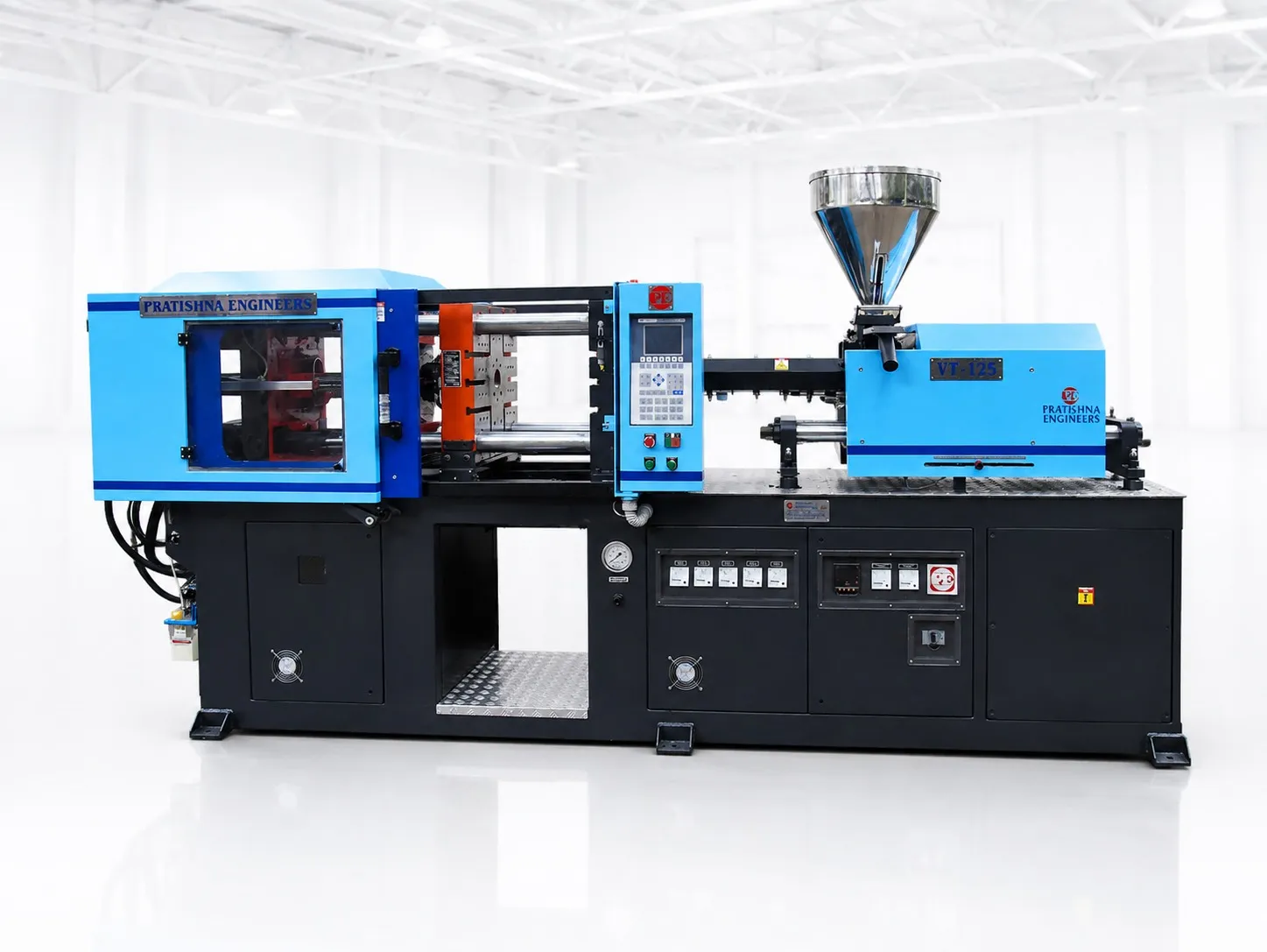
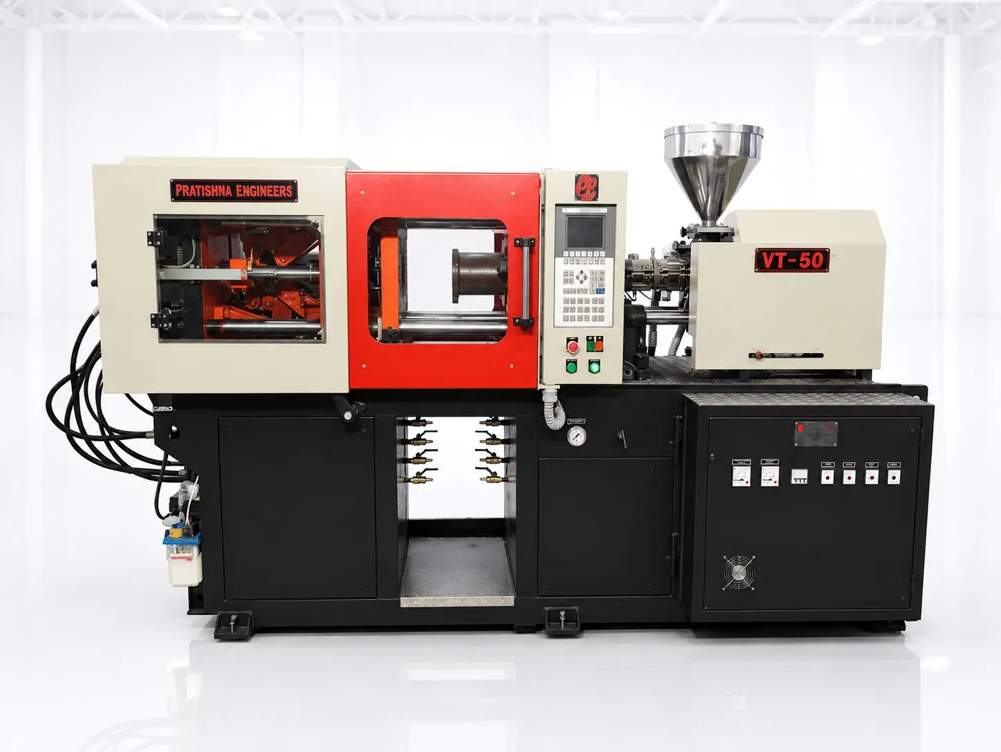
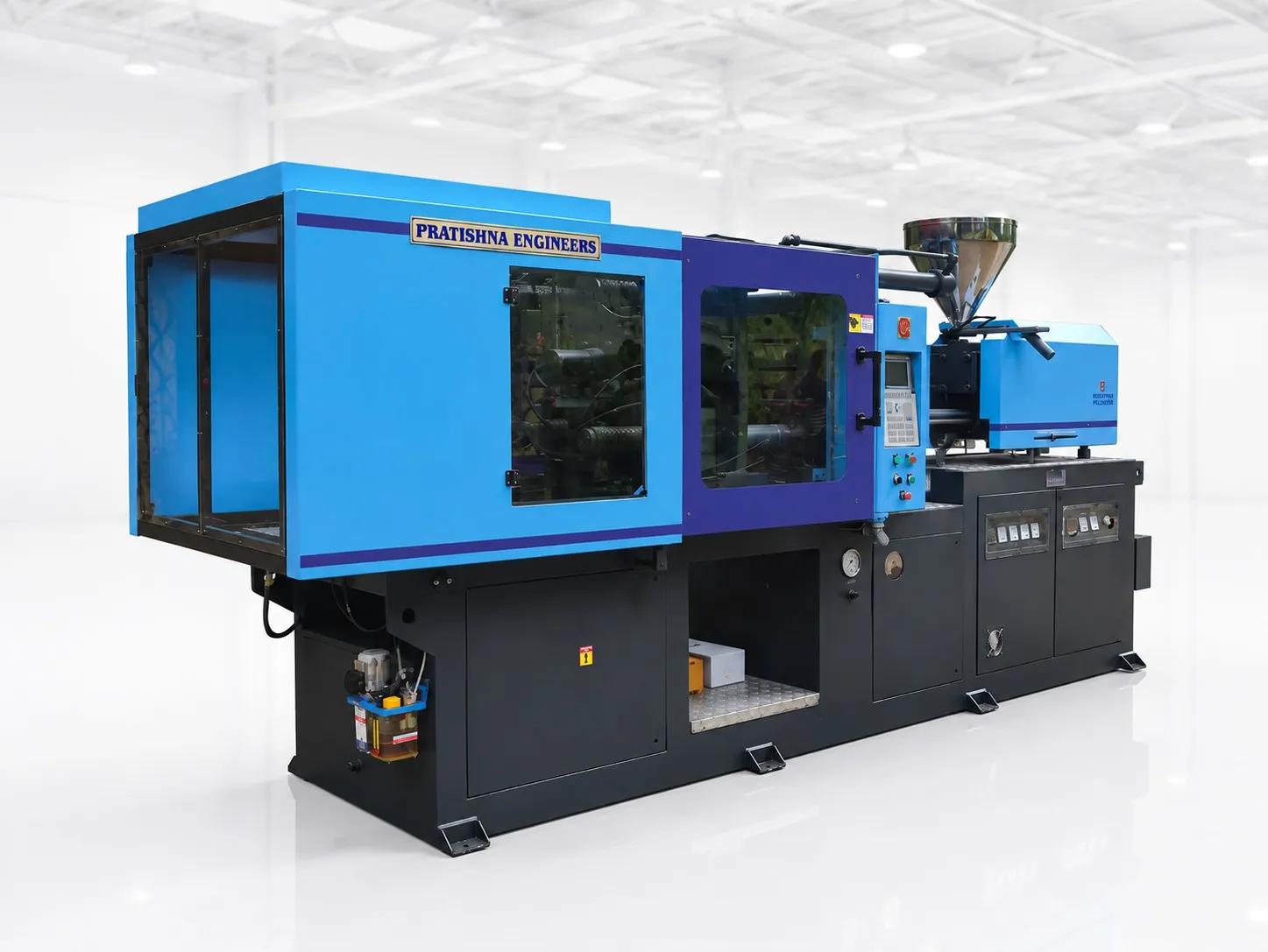
Send the mould's outside width, height and shut height, the locating ring size, the ejector layout, the part's projected area and depth, the resin grade and cavities. With those, the clamp, tie-bar, minimum-mould and stroke checks can be run on both sizes. See the 165 ton horizontal injection moulding machine page.
Frequently Asked Questions About 165 Ton vs 180 Ton Injection Moulding Machines
Can a mould be wider than the tie-bar space?
Not if it is loaded between the bars from above, because its width must pass the gap. Its height can be more than the vertical gap. Some machines offer tie-bar pulling, where one bar is withdrawn to load a wider mould; if you need that, ask for it at the enquiry stage.
Is tie-bar space measured centre to centre or clear?
Check which one the datasheet shows before you compare a mould with it. The clear distance between the bars, horizontal by vertical, is what the mould must pass. If a sheet gives centre distances instead, subtract one bar diameter to get the clear gap, and ask the supplier if the sheet does not say.
What is the difference between daylight and stroke?
Stroke is how far the moving platen travels. Daylight is the largest gap between the platens with the clamp fully open. On a toggle machine, daylight is the maximum mould shut height plus the stroke, so the full stroke is available whatever the mould's thickness within the machine's range.
Does the bigger machine use more power for the same mould?
It can, especially on a hydraulic machine, where much of the energy goes to base load whatever the part, as the applications article in this series explains. If the mould and part fit both frames, the smaller machine can run them for less. Measure both on the actual job if you can.
Why do flash marks appear in the middle of a mould?
Centre flash can mean the mould is too small for the platens, so they bow when clamped. Plastics Technology's setting guide links this to moulds covering less than about 70% of the tie-bar distance. Low clamp, worn platens or poor mould support can cause it too, so check each.
Related Articles
- What Can You Make on a 165 Ton Injection Moulding Machine?
- 165 Ton Machine for Pipe Fittings and Plumbing Parts
- Moulding Appliance Parts on a 165 Ton Machine
Sources & References
- MoldMaking Technology, B. Catoen: Machine Sizing and Specification for Optimal Mold Performance, Part 1 (Aug 2025)
- Plastics Technology, P. Witaszek, J. Klees, J. Fattori, E. Di Siro, J. Bozzelli: How to Mount an Injection Mold (June 2017)
- Plastics Engineering (SPE), A. Urbina: Mastering Clamping Force Calculation
- Reliance Industries: Repol H110MAS technical data sheet (July 2024)
Technical Disclaimer
Disclaimer: The information provided in this document is for general informational and educational purposes only. It is based on technical references and industry information available at the time of preparation and may be subject to change. It does not constitute engineering, technical, commercial or professional advice, nor does it constitute a quotation, specification, warranty or contractual commitment by Pratishna Engineers.
Actual injection moulding machine and process requirements vary according to the component design, material, mould, production volume, machine configuration and operating conditions. The information, examples, calculations and recommendations provided should be independently evaluated and verified for the specific application before making any equipment, process or production decision. Information obtained from third-party sources remains subject to the accuracy and limitations of those sources.
Limitation of Liability: Pratishna Engineers makes no representation or warranty, express or implied, regarding the completeness, accuracy or suitability of the information for any particular application. To the extent permitted by applicable law, Pratishna Engineers shall not be liable for any loss, damage, cost or consequence arising from reliance on or use of the information contained in this document. Final machine selection, configuration and application suitability should be confirmed with Pratishna Engineers based on complete and accurate project requirements.