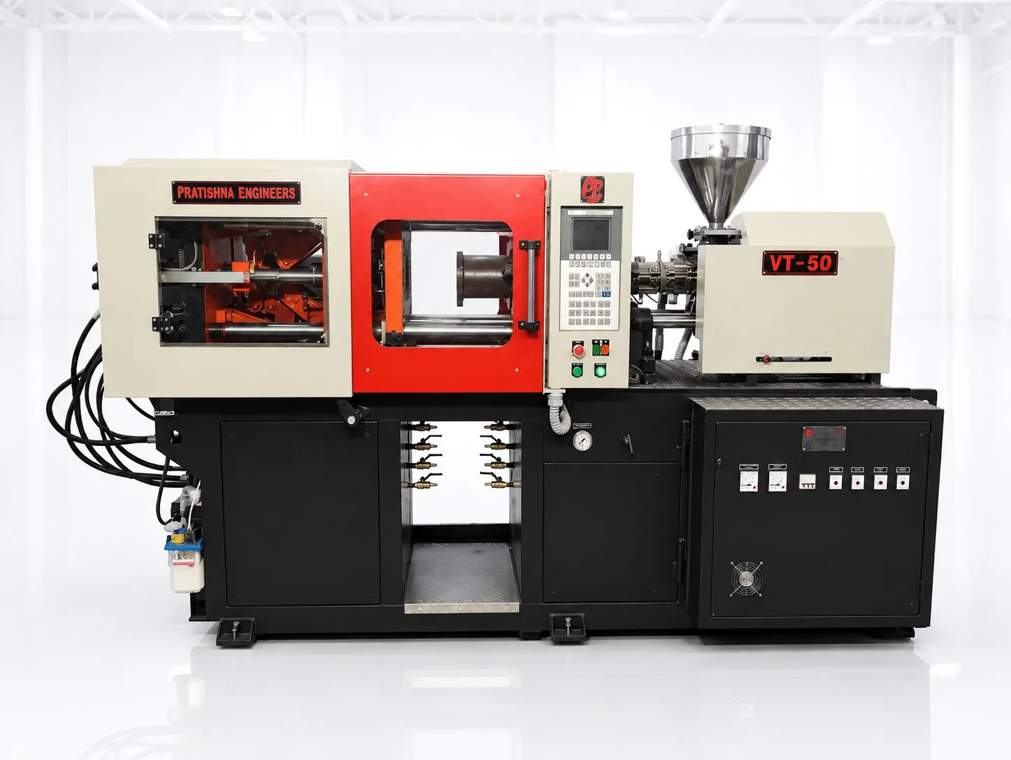
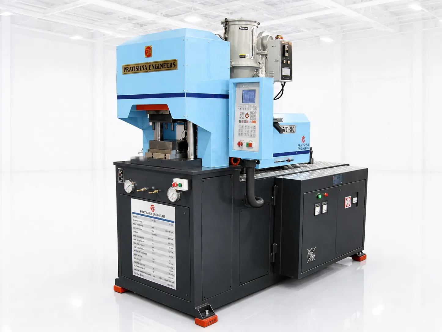
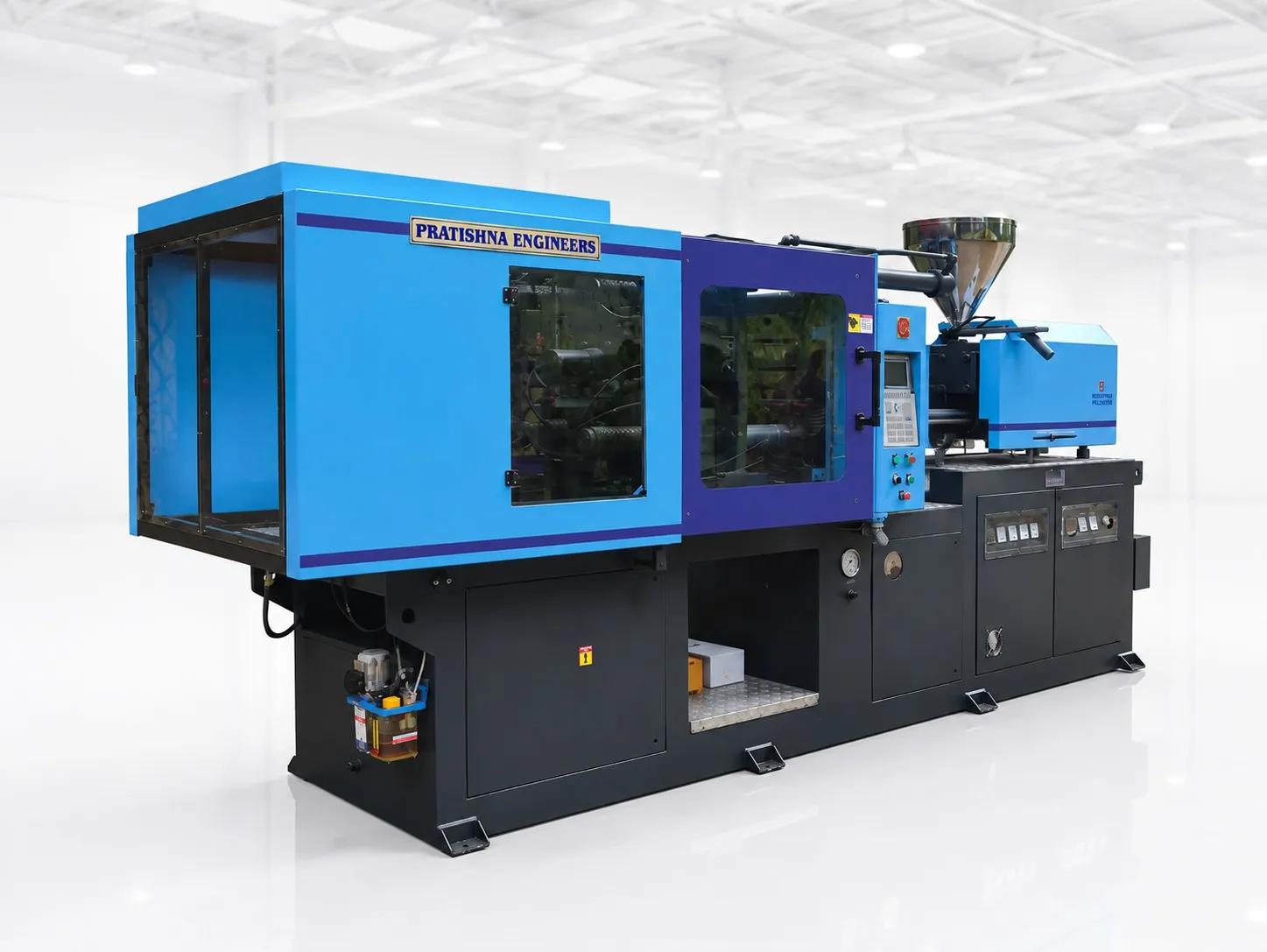
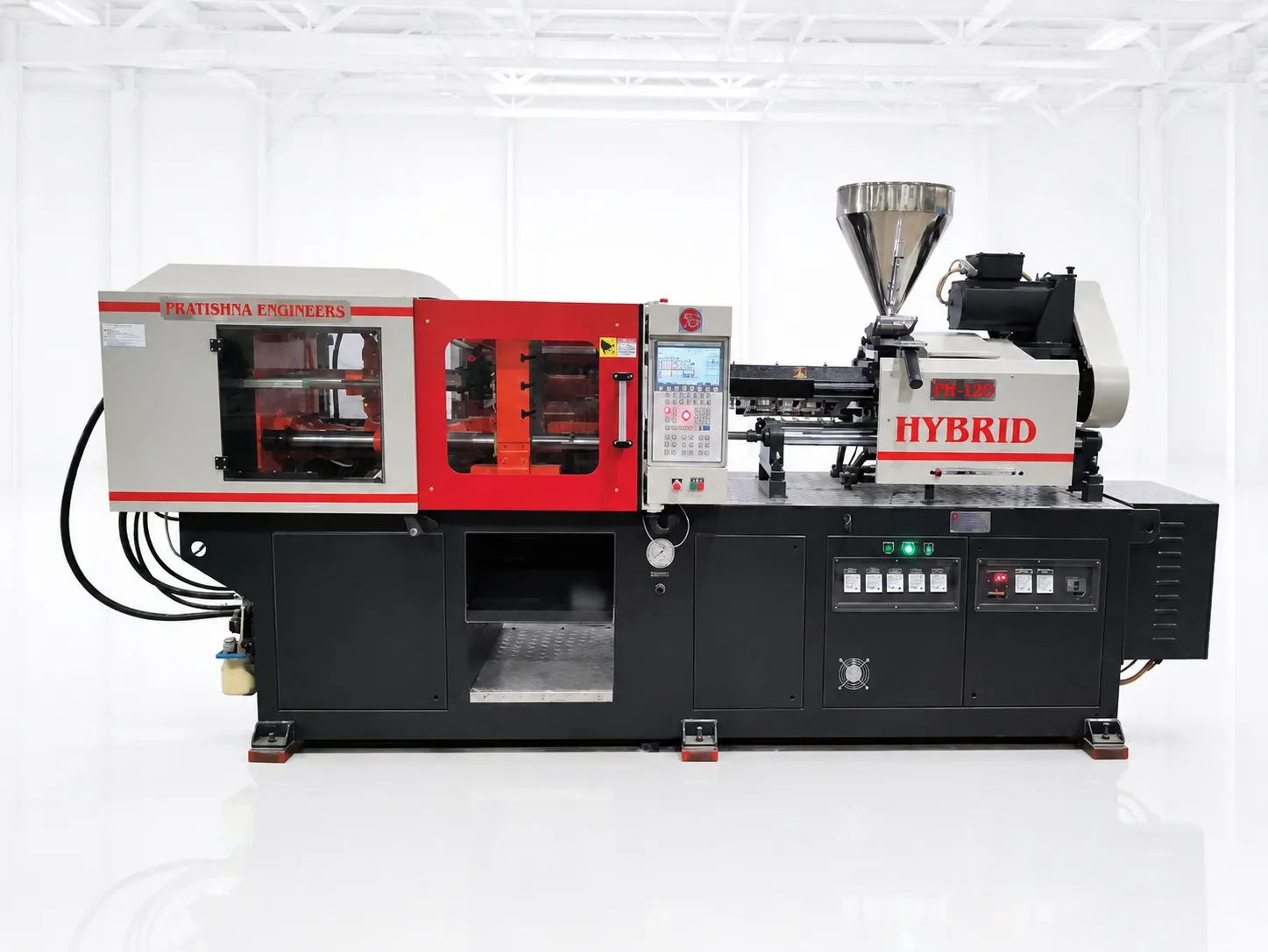
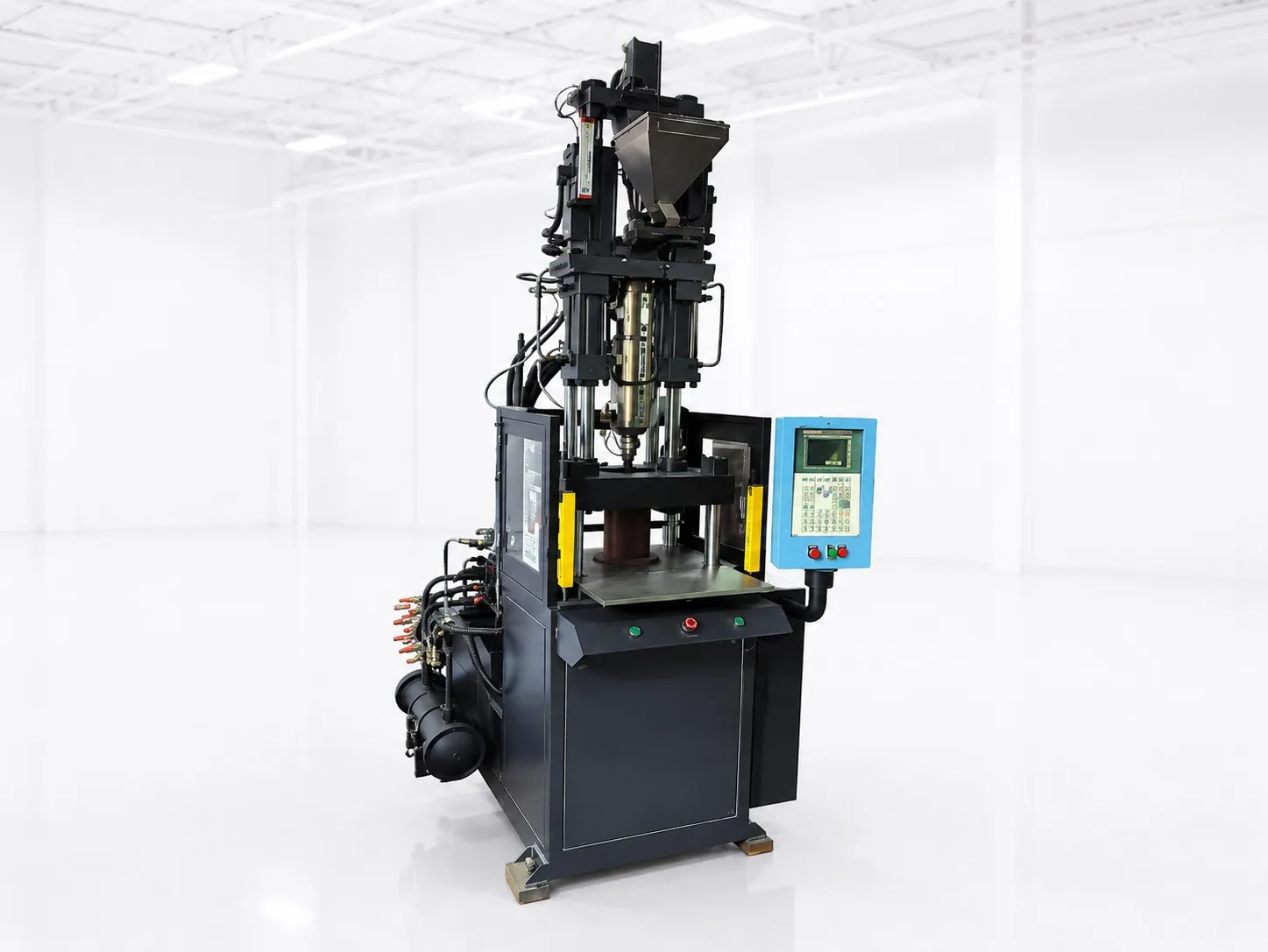
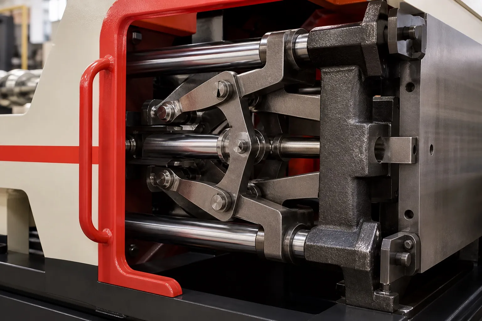

Horizontal clamp or vertical clamp: the two vertical-injection layouts compared
| Point | Horizontal clamp, injection from above | Vertical clamp, injection from above |
|---|---|---|
| How the mould opens | Sideways, parting line vertical | Upward, lower half faces up |
| Where melt enters | At the parting line, from above | Through the upper half, from above |
| What holds the insert | Grooves and clamps at the parting line | Gravity, in pins or pockets of the lower half |
| Typical parts | Cables, wires, moulded plugs, grommets | Pins, terminals, threaded bushes, multi-insert housings |
| Loading aids | Cable stops and outside clamps | Double-slide or rotary lower halves |
Choose by how the insert enters and leaves the mould, not by tonnage. If a cable or long insert has to pass right through the mould, a horizontal clamp with injection at the parting line gives it a clear path. If loose pins, terminals or bushes drop into the mould, a vertical clamp holds them by gravity.
Both layouts put the injection unit above the mould. The difference is the direction the mould opens, and that sets what can be loaded, how it is held while the melt arrives, and how the finished part comes out. Clamp force and shot size are worked out the same way on either machine.
Key Takeaways
- Cables and leads that exit the mould on one or both sides point to a horizontal clamp with parting-line injection.
- Loose inserts placed into pockets point to a vertical clamp, which also allows sliding or rotary lower halves.
- Clamp force, mould fit and opening stroke are checked the same way for both layouts and seldom separate them.
- Moulds are built for one layout; a mould cannot move between the two without being redesigned.
When does a horizontal clamp suit the part better?
When the part is moulded onto something that runs through the mould: a cable, a wire bundle, a cord with crimped pins, or a long rod. The parting line is vertical, the lead lies across it in grooves, and the injection unit fills from above without crossing the lead.
Cable grommets, strain reliefs, moulded plugs and wire harness clips all fit this pattern. The operator lays the lead in by hand, closes the guard, and the lead hangs clear of the mould. The wire overmoulding article in this series covers groove sizing and flash control on these jobs.
A vertical clamp can mould onto a short cable end that points upward out of the lower half, but long leads then have to be coiled or supported above the mould, and the clamp closes down onto them. For leads longer than a short tail, that handling becomes the bottleneck, and the risk of trapping a lead under the closing half rises with every extra cavity.
When does a vertical clamp suit the part better?
When loose inserts are placed into the mould: brass pins, terminals, threaded bushes, or several inserts per part. The lower half faces upward, so gravity keeps each insert seated in its pin or pocket while the upper half closes, with no magnets, clips or vacuum needed.
The vertical clamp also allows a second lower half on a sliding or rotary table, so inserts are loaded on one half while the other is moulded. A published insert moulding cost model, the aPriori guide, treats vertical as the default orientation for insert moulding and models those two-station tables.
Check the loading time before choosing the table. A second lower half saves the shorter of the clamp-closed time and the loading time, minus the table move, so it pays when loading takes about as long as the moulding. When inserts go in quickly, a fixed lower half is simpler and needs less tooling.
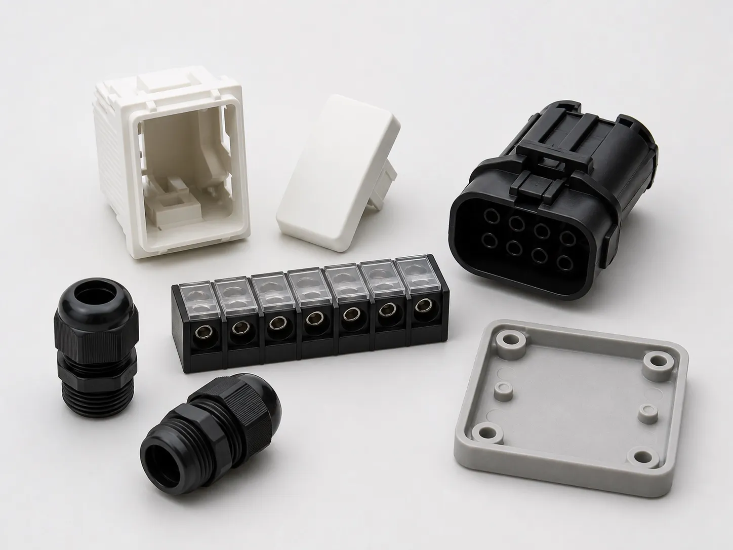
Several Indian electrical accessories under compulsory certification fit this side. The Electrical Accessories (Quality Control) Order, 2023 made the BIS Standard Mark compulsory for switch-socket-outlets to IS 15787, bayonet lamp holders to IS 1258 and boxes and enclosures to IS 14772, all parts that can carry pins, contacts or bushes placed into a lower mould half.
Horizontal clamp or vertical clamp: do clamp force or mould size decide?
Rarely on their own. Clamp force follows projected area times a tonnage factor for the resin, and the mould must fit the platens and open far enough to release the part, whichever way the clamp moves. Run those checks, then let the insert decide the layout.
A MoldMaking Technology sizing guide sets the basics: the mould should ideally sit within the tie bars, with at least the parts' projected area inside them, and the opening stroke should be at least 2.5 times the part height. It must also be thick enough for the minimum shut height and thin enough for the maximum.
The insert can still change the mould size. Cable grooves and long inserts that cross the parting line add mould width, and on a horizontal clamp that width runs between the tie bars, so check the cable pitch and the number of cavities against the space available before fixing the layout of the mould.
Our flat view: if the part has a lead longer than the mould, buy a horizontal clamp; if it has loose inserts and a short or no lead, buy a vertical clamp. Tonnage then picks the size within that layout, not the layout itself. Buying the wrong layout costs far more than buying the wrong tonnage, because every mould you build afterwards inherits it.
What should you send to choose the right clamp layout?
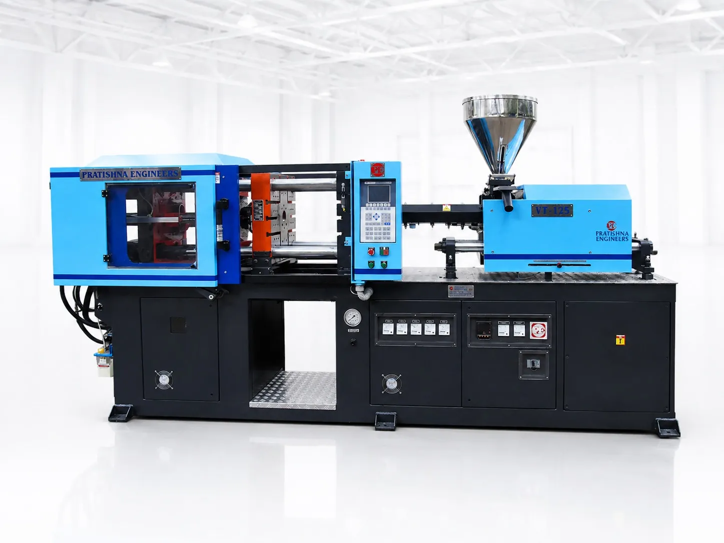
Send the part drawing, the insert or cable details with lead lengths, the number of inserts per part, the material, the cavity count and the output you need. See the horizontal clamp vertical injection machines page for the layout that suits cable and lead jobs.
Frequently Asked Questions About Horizontal and Vertical Clamps
Can a vertical clamp machine mould onto cables at all?
Yes, for short cable ends that can point upward out of the lower half, such as a short pigtail with a moulded connector. Long cables are harder, because they must be supported above the mould and kept clear of the closing upper half, which slows loading and risks trapping the cable.
Which layout is easier to automate?
Insert jobs on a vertical clamp can be simpler to automate, because a pick-and-place unit drops inserts straight down into an upward-facing mould and a sliding or rotary table gives it a station to work on. Cable jobs need the lead fed, laid and clamped, which is harder for a robot.
Can the same mould run on both layouts?
No. A mould is built for one clamp direction and one injection point. A horizontal clamp mould takes melt at the parting line from above, while a vertical clamp mould takes it through the upper half. Moving a job between the two means a new or heavily reworked mould.
Which layout suits a moulded grommet on a long cable?
A horizontal clamp with injection at the parting line. The cable lies across the open mould in grooves, the halves close sideways around it, and the lead hangs clear on both sides. On a vertical clamp the same cable would have to be routed up and out of the lower half.
What if the part has both a cable and loose pins?
Look at what dominates the handling. If the pins are crimped to the cable first, the job is a cable job and suits a horizontal clamp. If the pins are separate inserts and the cable is a short tail, a vertical clamp may load faster. A timed trial of both loading sequences settles it.
Related Articles
- Cable and Wire Overmoulding on PV Series Vertical Machines
- Moulding Plugs on Power Cords: Machine and Mould Setup
- PVC Moulding for Plugs and Grommets: Temperature and Screw Care
Sources & References
- MoldMaking Technology, B. Catoen: Machine Sizing and Specification for Optimal Mold Performance, Part 1 (Aug 2025)
- aPriori: Cost Model Guide: Insert Injection Molding Options
- Gazette of India (DPIIT): Electrical Accessories (Quality Control) Order, 2023
- GEON Performance Solutions: Injection Molding Guide: GEON PVC Molding Formulations (PG0019BC, 2021)
Technical Disclaimer
Disclaimer: The information provided in this document is for general informational and educational purposes only. It is based on technical references and industry information available at the time of preparation and may be subject to change. It does not constitute engineering, technical, commercial or professional advice, nor does it constitute a quotation, specification, warranty or contractual commitment by Pratishna Engineers.
Actual injection moulding machine and process requirements vary according to the component design, material, mould, production volume, machine configuration and operating conditions. The information, examples, calculations and recommendations provided should be independently evaluated and verified for the specific application before making any equipment, process or production decision. Information obtained from third-party sources remains subject to the accuracy and limitations of those sources.
Limitation of Liability: Pratishna Engineers makes no representation or warranty, express or implied, regarding the completeness, accuracy or suitability of the information for any particular application. To the extent permitted by applicable law, Pratishna Engineers shall not be liable for any loss, damage, cost or consequence arising from reliance on or use of the information contained in this document. Final machine selection, configuration and application suitability should be confirmed with Pratishna Engineers based on complete and accurate project requirements.