
238 t. That is the clamp for eight 100 ml PP cups with a 70 mm rim in a single-face mould, at a thin-wall factor of 5 US t/in² with a 10% reserve. At a factor of 8, the same eight cups need 381 t. Put them in a two-level stack, four per face, and the figure at factor 8 drops to about 210 t.
So a high-cavity thin-wall mould on a 260 t machine is possible, but the cavity count depends on the flow ratio, the mould type and an injection unit sized for small, fast shots.
Key Takeaways
- Thin-wall parts have flow length to wall ratios of about 100:1 to 200:1 and a published clamp range of 5 to 8 US t/in², against 3 to 5 for conventional moulding.
- A stack mould needs the clamp of one face plus about 10% per extra level, so it can nearly double cavities on the same press.
- Thin-wall shots should use at least 40% of the barrel, so a barrel sized for pails can be far too large for cups.
- Published thin-wall fill times are under one second, with injection speeds above 76 mm/s and often 152 mm/s.
How Many Thin-Wall Cavities Can 260 t Carry?
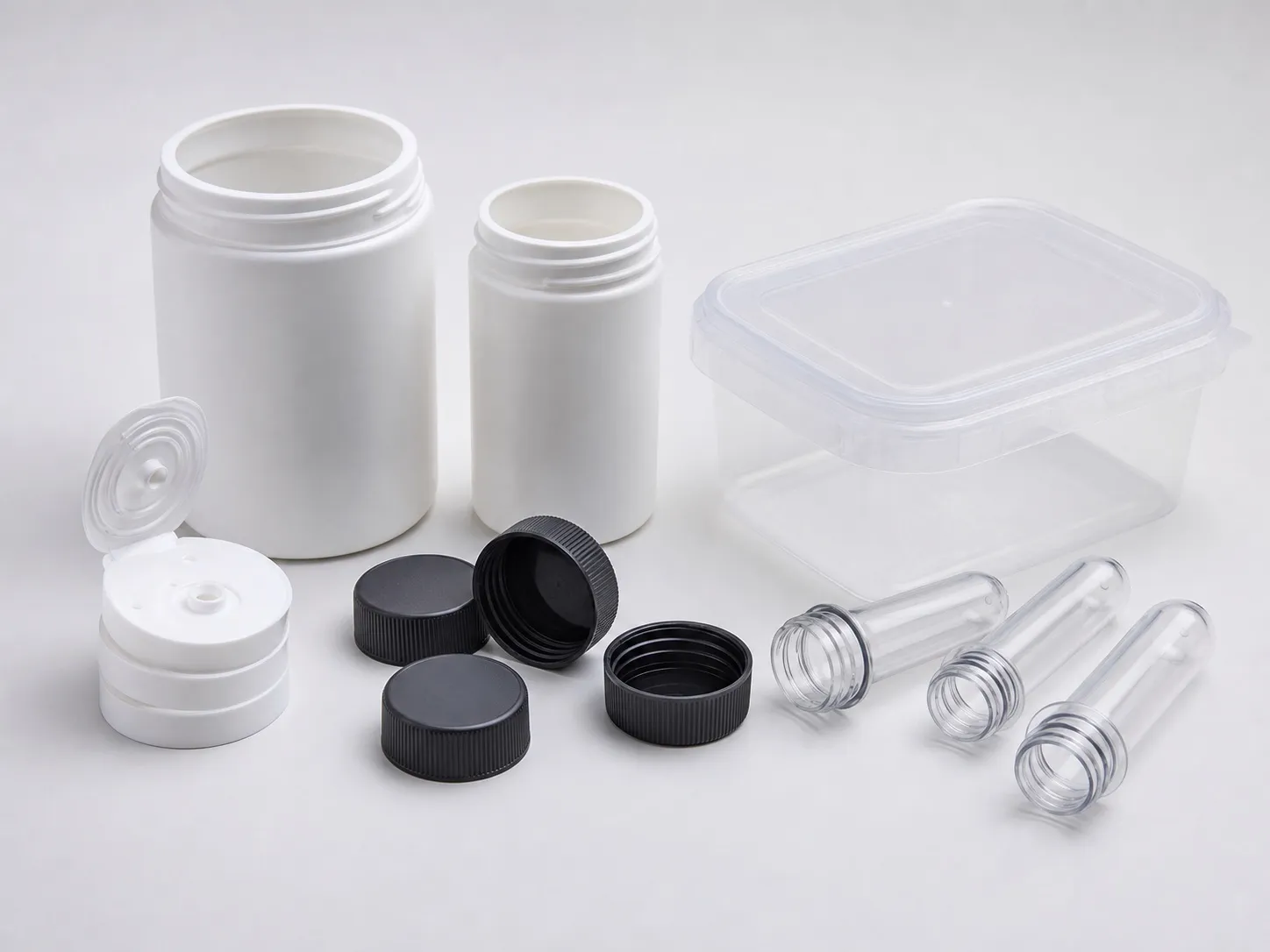
Five to eight 100 ml cups, three to five 250 ml tubs or two to three 500 ml tubs in a single-face mould. A two-level stack lifts these to eight to fourteen cups, six to ten small tubs or two to four larger tubs, depending on the factor.
Cavities a 260 t clamp can carry at thin-wall factors (calculated, hot runner, 10% reserve; rim sizes are assumptions)
| Part | Rim | Area | Single face (factor 8 to 5) | Two-level stack (factor 8 to 5) |
|---|---|---|---|---|
| 100 ml cup | 70 mm | 38.5 cm² | 5 to 8 | 8 to 14 |
| 250 ml tub | 85 mm | 56.7 cm² | 3 to 5 | 6 to 10 |
| 500 ml tub | 115 mm | 103.9 cm² | 2 to 3 | 2 to 4 |
The factor depends on the flow ratio. A PlasticsToday article by Gary Tremblay of Sabic Innovative Plastics puts thin-wall designs at flow length to wall ratios of about 100:1 to 200:1. A cup gated at the base with 90 mm of flow and a 0.5 mm wall sits at 180:1, near the top.
Tremblay gives clamp of 5 to 8 US t/in² for thin-wall work, about 0.703 to 1.125 t/cm², against 3 to 5 for conventional parts. Thin-wall resins need high flow and must withstand shear heating of 50,000 s⁻¹ or more. The general clamp method is in the container applications article in this series.
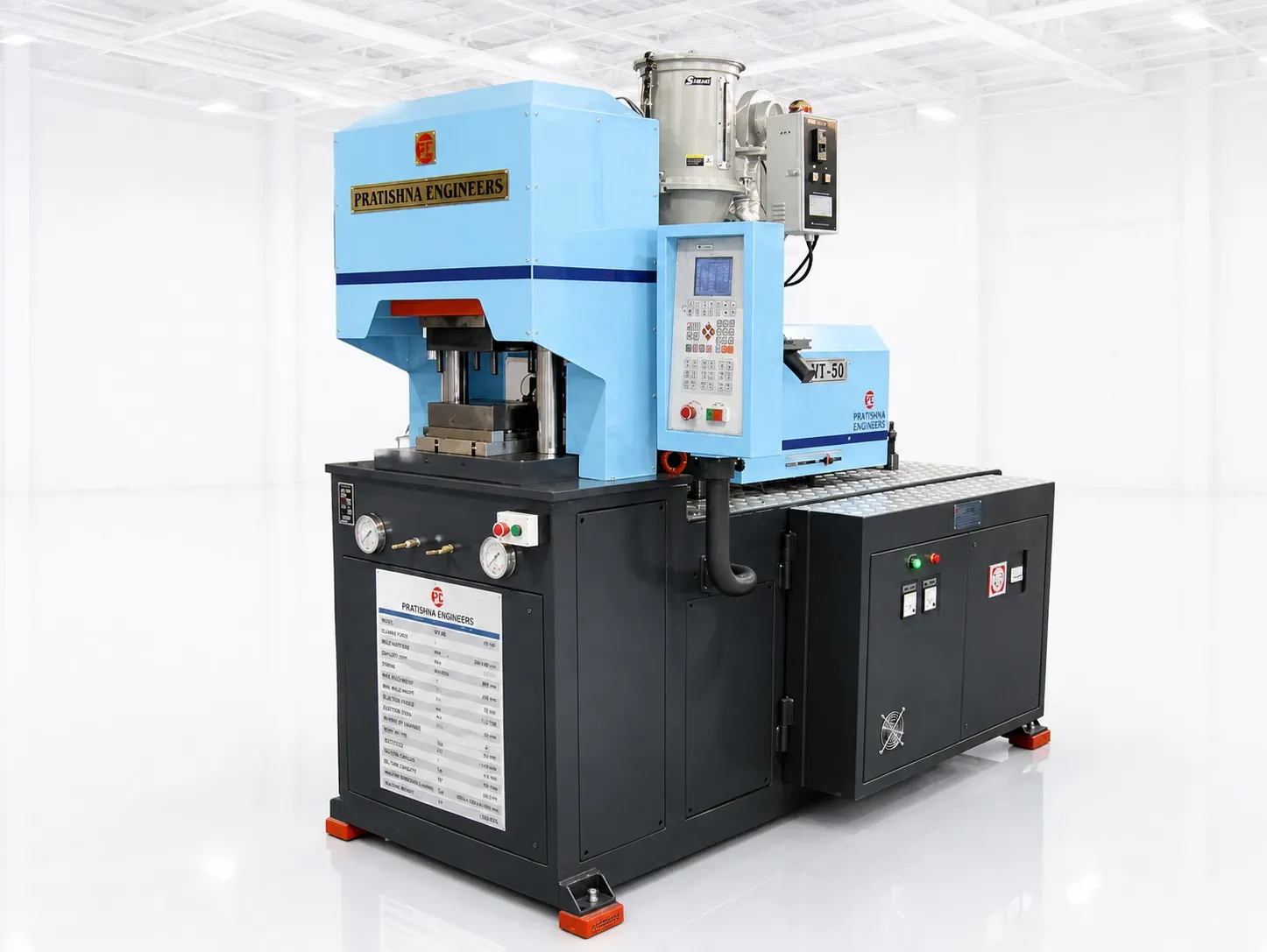
The stack columns rest on Catoen's MoldMaking Technology guidance that a stack mould needs the clamp of one face plus 10% per extra level. The catch is size: a stack mould is taller and heavier, so check shut height, opening stroke and the load on the moving platen before you count on doubled cavities.
What Must the Machine Deliver for a High-Cavity Thin-Wall Mould?
Speed, pressure, stiffness and the right barrel. Tremblay lists injection pressures above 30,000 psi (about 2,109 kg/cm²), speeds above 76 mm/s and often 152 mm/s, and fill times under one second. Platens must stay flat at those pressures, and the shot must suit the barrel.
His article describes thin-wall machines with accumulator-assisted clamps and extra-thick platens; on better machines, tie-bar distance to platen thickness is 2:1 or less. Bob Catoen's MoldMaking Technology article puts dry cycles at 1 to 2.5 s for thin-wall machines, against 3 to 5 s for others.
The barrel is the trap on a 260 t press. Tremblay says a thin-wall shot should use at least 40% of the barrel, because a large barrel may not give the pressure boost and lets the melt degrade. Eight cups weigh far less than one pail, so the injection unit that suits pails rarely suits cups.
Our view: for high-cavity thin-wall work, specify the injection unit for the cup and the clamp for the mould, as two separate decisions. A 260 t clamp with a pail-sized barrel will run cups badly however many cavities the mould has.
How Should the Mould Be Built and Balanced?
Stiff, vented and balanced so every cavity fills in the same time. With eight or more cavities, a hot runner keeps runner area out of the clamp sum and evens the fill. Steel, support and cooling must stand up to cavity pressures far above conventional moulding.
Tremblay recommends steels harder than P-20, thicker plates, as many support pillars as fit with a small preload, and interlocks. Demanding parts vent core and ejector pins as well as the parting line. For cooling he favours larger lines for more flow over colder coolant.
A high-cavity mould has one advantage on a large press: it is wide enough to support the platens. A Plastics Technology mounting guide suggests the mould cover at least 70% of the tie-bar distance, which a two-cavity cup mould on 260 t may not reach, as the container applications article in this series explains.
Resin choice matters as much as steel. Reliance's Repol H110MAS, a nucleated PP homopolymer for rigid packaging with IS 10910 food-contact compliance, has an MFR of 11 g/10 min. Flow ratios near 200:1 can need a higher-flow grade, so ask your resin supplier for a thin-wall grade before the mould-filling analysis.
What Should You Send Before Ordering a Thin-Wall Mould?
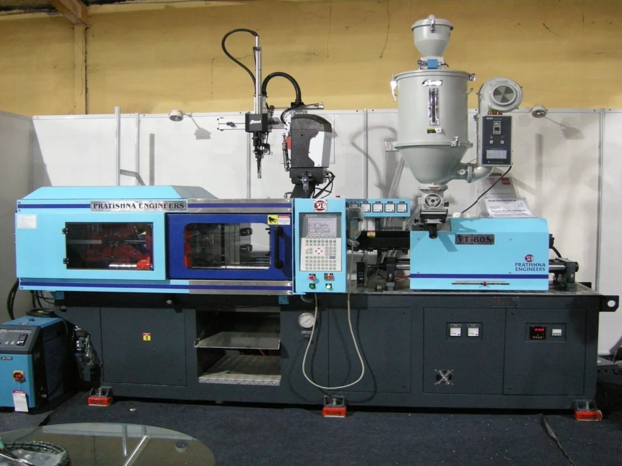
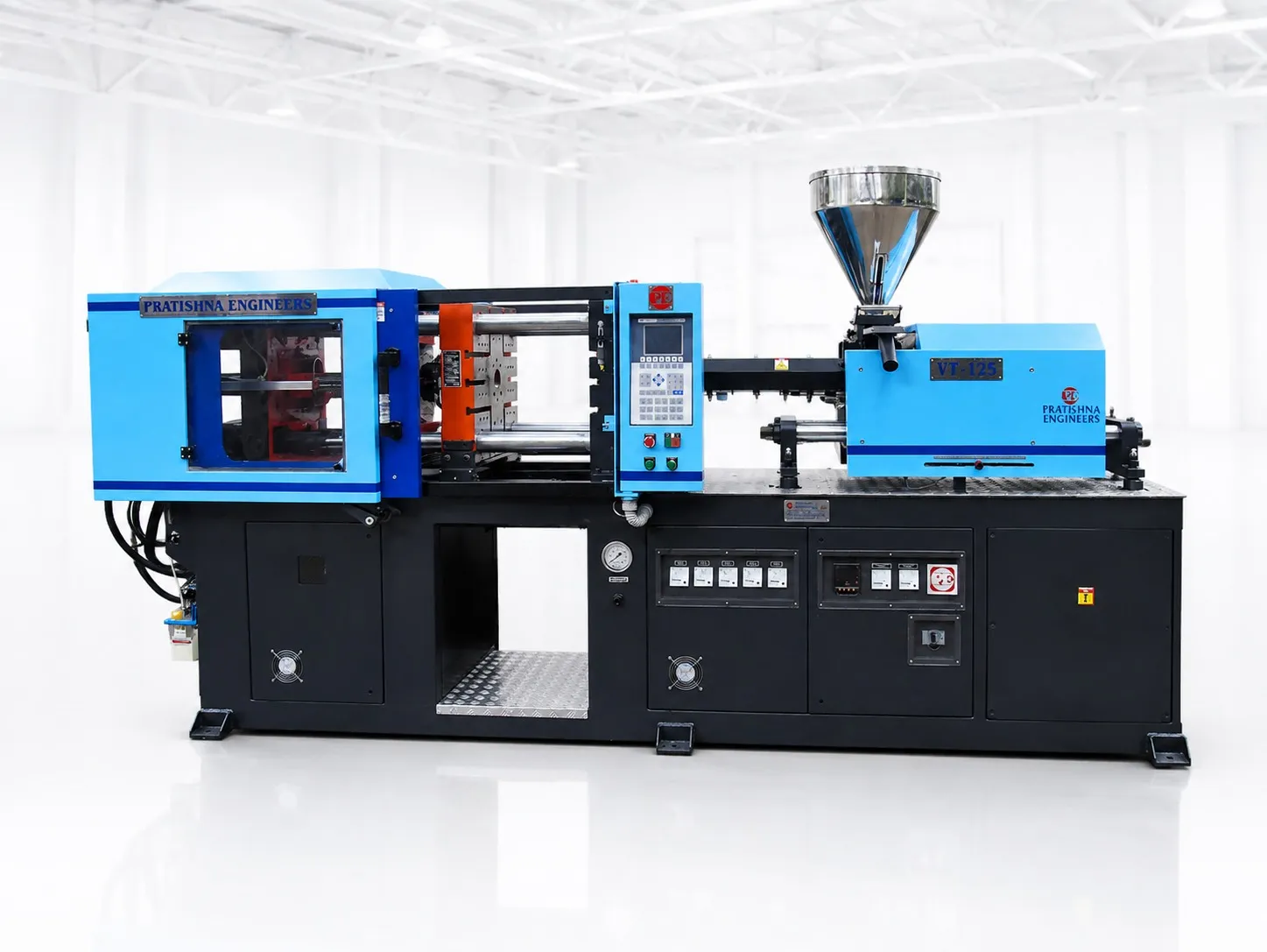
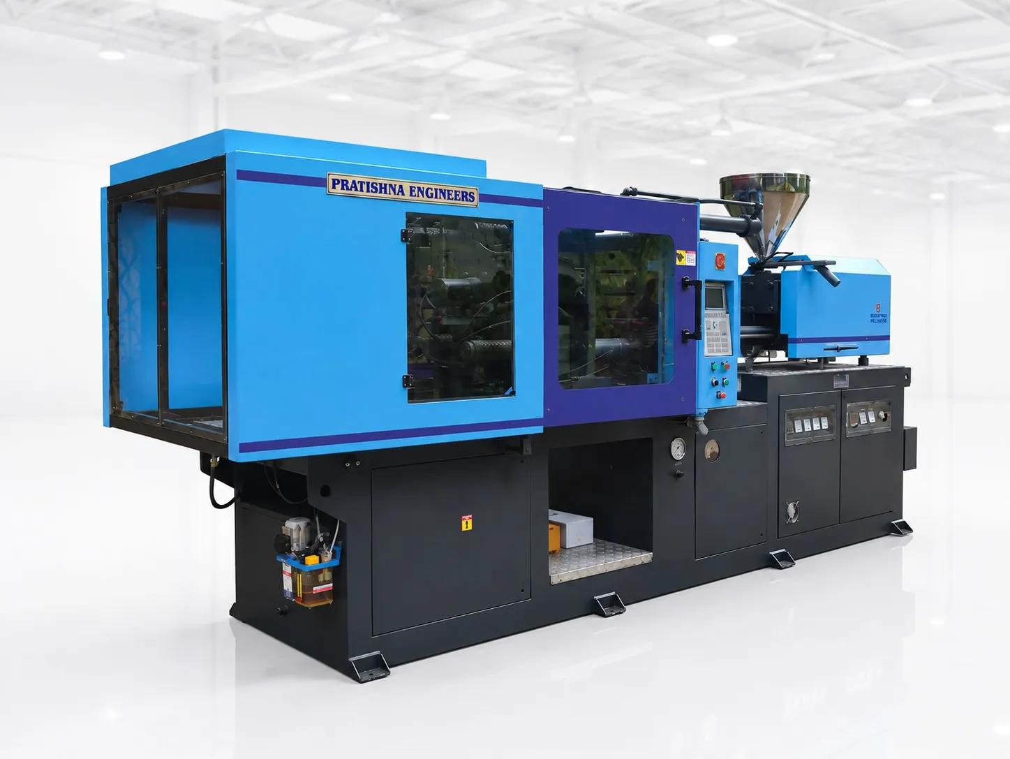
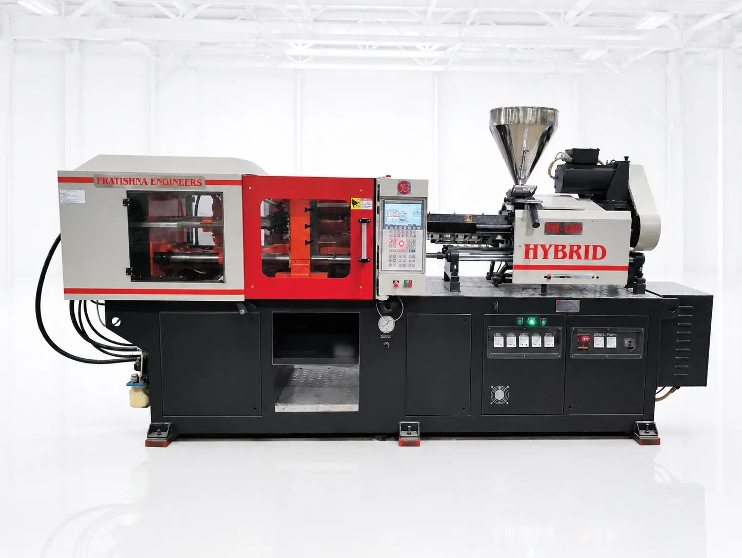
Send the part drawing with rim, wall and gate position, the part weight, the resin grade, the cavity count you want and whether a stack mould is an option. With these, clamp, shot share, fill rate and mould size can be checked together. See the 260 ton horizontal injection moulding machine page.
Frequently Asked Questions About High-Cavity Thin-Wall Moulds
Why do outer cavities short-fill on a high-cavity mould?
One likely cause is a runner that is not balanced, so outer cavities see more pressure drop and colder melt. Hot runner zones that run at different temperatures cause the same pattern. Check each zone, then compare part weights cavity by cavity. Weight differences point to the cavities that fill late before you raise speed or pressure.
Does a stack mould slow the cycle?
It can add time, because the mould opens further and both faces must eject and clear. The gain is cavities per shot, often close to double. Compare parts per hour for both layouts using the dry cycle at the stroke the stack needs, not the shortest stroke the machine offers.
Can a conventional press be adapted for thin-wall work?
Tremblay's article says adapting conventional machines is usually not a wise idea. Thin-wall work needs fast injection, high pressure, stiff platens and fine control at the same time. Adding an accumulator to a standard press may raise speed but leave the platens, control resolution or barrel size unsuited to the job.
How fine must the control be for thin-wall moulding?
Published thin-wall guidance lists control resolution of 0.04 in/s on speed, 1 bar on pressure, 0.004 in on position, 0.01 s on time, 1 rpm and 0.10 ton on clamp. At fill times under one second, coarse control shows up as alternating short shots and flash between cycles.
Is more ejection needed on thin-wall cups?
Yes. Thin walls shrink little, so they grip the core firmly. Tremblay's rule of thumb is double the ejector pins, each twice as large, with blade or sleeve ejectors on ribs and bosses. Air assist at the base of a cup core can also help release without denting the wall.
Related Articles
- What Can You Make on a 260 Ton Container Moulding Machine?
- Moulding Pails and Large Tubs on a 260 Ton Machine
- Sweet Boxes and Food Trays: Planning Output on a 260 Ton Machine
Sources & References
- PlasticsToday, G. Tremblay (Sabic Innovative Plastics): Never too thin
- MoldMaking Technology, B. Catoen: Machine Sizing and Specification for Optimal Mold Performance, Part 1
- Plastics Technology, P. Witaszek, J. Klees, J. Fattori, E. Di Siro, J. Bozzelli: How to Mount an Injection Mold
- Reliance Industries: Repol H110MAS Technical Data Sheet
Technical Disclaimer
Disclaimer: The information provided in this document is for general informational and educational purposes only. It is based on technical references and industry information available at the time of preparation and may be subject to change. It does not constitute engineering, technical, commercial or professional advice, nor does it constitute a quotation, specification, warranty or contractual commitment by Pratishna Engineers.
Actual injection moulding machine and process requirements vary according to the component design, material, mould, production volume, machine configuration and operating conditions. The information, examples, calculations and recommendations provided should be independently evaluated and verified for the specific application before making any equipment, process or production decision. Information obtained from third-party sources remains subject to the accuracy and limitations of those sources.
Limitation of Liability: Pratishna Engineers makes no representation or warranty, express or implied, regarding the completeness, accuracy or suitability of the information for any particular application. To the extent permitted by applicable law, Pratishna Engineers shall not be liable for any loss, damage, cost or consequence arising from reliance on or use of the information contained in this document. Final machine selection, configuration and application suitability should be confirmed with Pratishna Engineers based on complete and accurate project requirements.