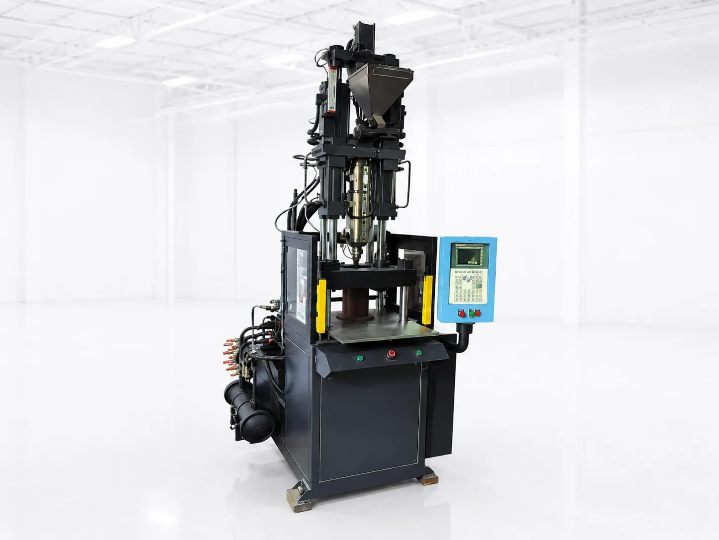
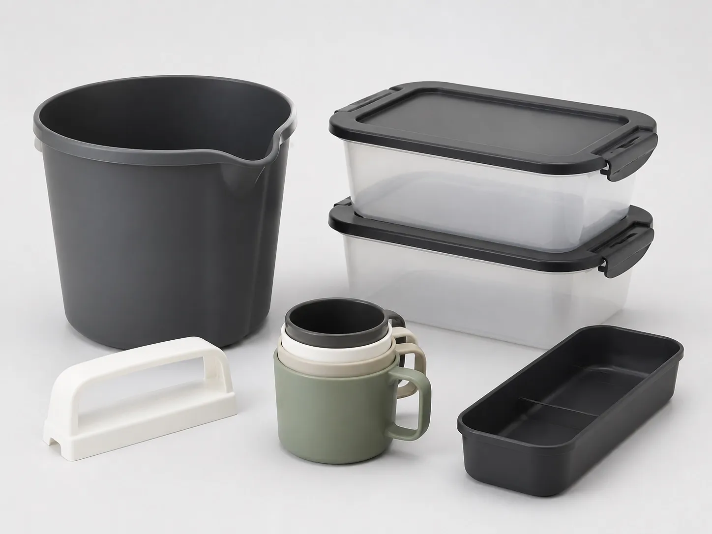

Short answer: hourly output is 3,600 divided by the cycle in seconds, times cavities, times the share of good shots. For dairy cup moulding output on a 180 t machine, clamp at thin-wall factors sets the cavity count and wall thickness sets the cycle. Four cavities at a 6 s cycle and 98% good shots give about 2,350 cups an hour, as an illustration, not a promise.
A real plan then has to allow for lids, changeovers, idle time and the food-contact paperwork. This article takes each in turn and ends with a monthly plan you can adapt.
Key Takeaways
- Hourly output = 3,600 ÷ cycle (s) × cavities × good-shot share, and each term is a separate planning lever.
- Wall thickness is squared in the cooling equation, so a wall 20% thinner needs about 36% less cooling time.
- Idling machines can draw 52% to 97.5% of their full moulding energy, so idle hours belong in the plan alongside running hours.
- Plan on a cycle proven in a trial with your mould and grade; a plan built on 5 s that runs at 6 s falls short by a sixth every hour.
How Do You Calculate Dairy Cup Moulding Output?
Multiply shots per hour by cavities and by the share of good shots. Shots per hour are 3,600 divided by the cycle in seconds. An 8 s cycle gives 450 shots an hour; with four cavities and 97% good shots, that is about 1,750 cups an hour.
Cups per hour by cycle and cavity count at a 98% good-shot share (calculated; cycles are illustrations, not machine claims)
| Cycle | 3 cavities | 4 cavities | 6 cavities |
|---|---|---|---|
| 5 s (720 shots/h) | 2,117 | 2,822 | 4,234 |
| 6 s (600 shots/h) | 1,764 | 2,352 | 3,528 |
| 8 s (450 shots/h) | 1,323 | 1,764 | 2,646 |
| 10 s (360 shots/h) | 1,058 | 1,411 | 2,117 |
The levers pull against each other. More cavities raise output per shot, but they also raise clamp, and at thin-wall factors a 180 t clamp carries only a few cups. The cavity counts that fit by clamp are set out in the container applications article in this series.
Good-shot share falls if outer cavities short-fill or rims flash, and every point lost comes straight off saleable output. Plan on effective hours, not clock hours: planned stops, mould and colour changes and start-up scrap all come off the day.
What Sets the Cycle Time for Cups and Small Tubs?
Cooling, once fill is fast enough. RJG's guidance on cooling time says wall thickness has the largest effect and is squared in the cooling equation. In its trial on a 3.3 mm ABS part in an eight-cavity mould, about 85% of the cycle was cooling.
Squaring works in your favour on thin walls. A 0.6 mm wall needs about 64% of the cooling of a 0.75 mm wall, because 0.8² is 0.64. RJG also notes that only about 40% of the heat must be removed before ejection, and suggests adding about 20% to the calculated cooling timer as a safety factor.
The rest of the cycle is mould movement, fill, hold and take-out. On a thin-wall cup these can be a large share of the total, so ask for the dry cycle at the opening stroke your cup mould needs, not at the shortest stroke the machine allows.
Cooling layout matters as much as water temperature. Gary Tremblay's PlasticsToday article on thin-wall moulds favours larger cooling lines for more flow rather than colder coolant, along with non-looped lines and high-conductivity inserts.
Small tubs follow the same rules with one difference: a deeper tub has a longer core, and the core is the hardest part of the mould to cool. If the tub sticks or ovalises after ejection, core cooling is the first place to look, before the cycle is lengthened.
Our view: plan on the cycle you have run on a trial, not the cycle you hope for. Every customer commitment downstream rests on that one number, and a dairy customer filling to a daily schedule will feel any shortfall within the first week.
How Do Lids, Changeovers and Idle Time Change the Plan?
Each takes hours away from the cup mould. A lid with the same rim needs similar clamp, so cups and lids either share one machine in campaigns or need two machines. Changeovers and start-up scrap come off effective hours, and idle time still draws power.
A PlasticsToday article by Robin Kent reports idling machines drawing 52% to 97.5% of their full moulding energy, and suggests idle periods longer than about 1.5 hours may be cheaper to switch off and restart. Group colour changes and lid campaigns into blocks to keep idle hours short.
Kent also notes that rising energy on the same job can point to screw or barrel wear. Logging kWh per thousand cups from the first week gives you a baseline to compare against.
For dairy packaging, PP must conform to IS 10910 and the pack must meet FSSAI migration limits, as the thin-wall article in this series explains. Schedule IV of the FSSAI Packaging Regulations 2018 also suggests PP or HDPE caps for milk, fats and oils, which is worth noting if the cup ships with a moulded lid.
What Should You Send to Plan Output?
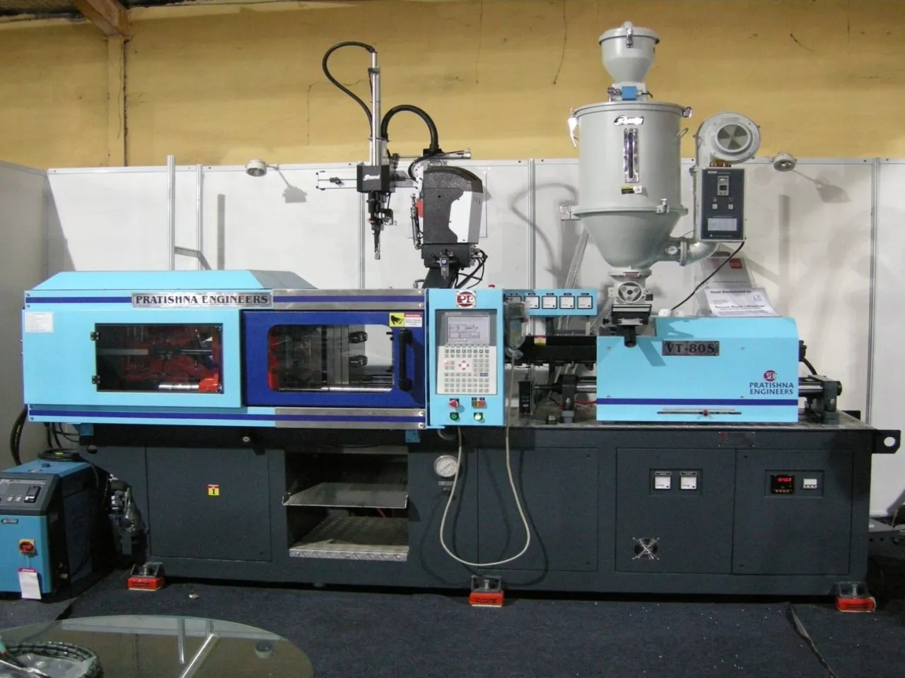
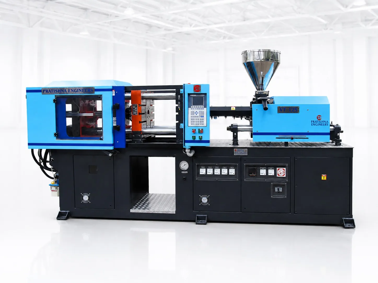
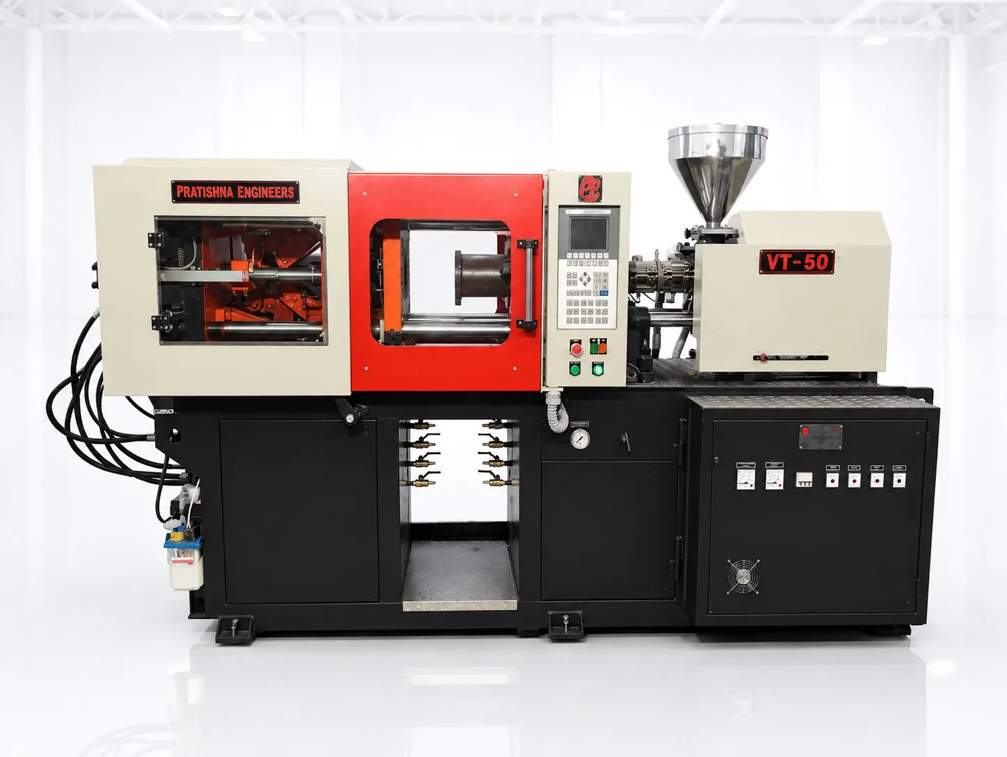
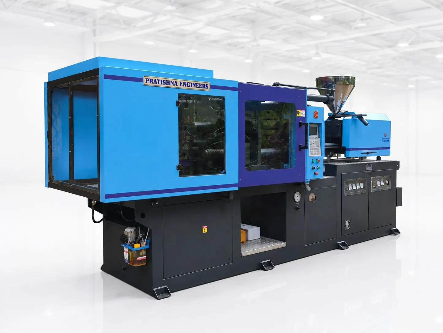
Send the cup and lid drawings with rim size and wall thickness, the resin grade, the monthly volume, the number of colours and the shifts you run. With those, cavity count, cycle and effective hours can be planned before the mould is ordered. See the 180 ton horizontal injection moulding machine page.
Frequently Asked Questions About Dairy Cup Moulding Output
How many cups an hour can a 180 t machine make?
There is no single figure, because it depends on cavities, cycle and good-shot share. Work it out as 3,600 divided by the cycle in seconds, times cavities, times the good-shot share. Then confirm the cavity count against clamp at the thin-wall factor, and the cycle on a trial with your mould and grade.
Should dairy cups and lids run on separate machines?
If the volume justifies it, separate machines avoid mould changes and let each tool run at its own cycle. With one machine, run lids and cups in campaigns sized to your stock levels. A lid's flat area can need clamp similar to the cup, so check both before assigning them to one press.
Does in-mould labelling change output?
It can. A robot has to place the label in the cavity before each shot, which adds time to the cycle and another source of rejects if a label shifts or folds. Plan labelled output from a trial with the label system running, not from the bare moulding cycle of an unlabelled cup.
How much does good-shot share matter on a cup job?
A great deal at high volume. At four cavities and a 6 s cycle, falling from 98% to 95% good shots loses about 72 cups an hour. Over 22 effective hours a day for 26 days, that is about 41,000 cups a month, before counting the resin and regrind handling for the rejects.
Can colder chilled water shorten a cup cycle?
Only up to a point. Wall thickness has the largest effect on cooling time, and thin-wall mould guidance favours larger cooling lines and more flow over colder coolant. Very cold water can also cause condensation on the mould surface in humid weather, which marks cups and can rust the steel.
Related Articles
- What Can You Make on a 180 Ton Container Moulding Machine?
- Moulding Thin-Wall Food Containers on a 180 Ton Machine
- 40 mm or 45 mm Screw? Choosing for Thin-Wall Packaging
Sources & References
- RJG Inc.: How to Determine Injection Molding Cooling Time
- PlasticsToday, R. Kent: Getting to know your real energy use and cost
- PlasticsToday, G. Tremblay (Sabic Innovative Plastics): Never too thin
- Food Safety and Standards Authority of India (FSSAI): Food Safety and Standards (Packaging) Regulations, 2018, compendium
Technical Disclaimer
Disclaimer: The information provided in this document is for general informational and educational purposes only. It is based on technical references and industry information available at the time of preparation and may be subject to change. It does not constitute engineering, technical, commercial or professional advice, nor does it constitute a quotation, specification, warranty or contractual commitment by Pratishna Engineers.
Actual injection moulding machine and process requirements vary according to the component design, material, mould, production volume, machine configuration and operating conditions. The information, examples, calculations and recommendations provided should be independently evaluated and verified for the specific application before making any equipment, process or production decision. Information obtained from third-party sources remains subject to the accuracy and limitations of those sources.
Limitation of Liability: Pratishna Engineers makes no representation or warranty, express or implied, regarding the completeness, accuracy or suitability of the information for any particular application. To the extent permitted by applicable law, Pratishna Engineers shall not be liable for any loss, damage, cost or consequence arising from reliance on or use of the information contained in this document. Final machine selection, configuration and application suitability should be confirmed with Pratishna Engineers based on complete and accurate project requirements.