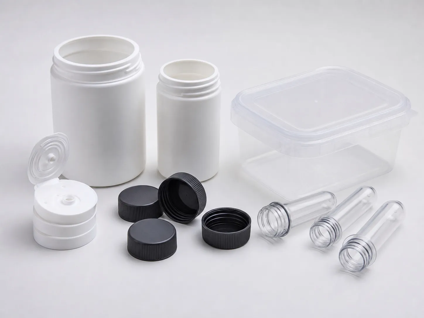

Twenty-four cavities on a 7.0 s cycle and 32 cavities on a 9.3 s cycle make almost the same number of caps: about 12,340 and 12,390 an hour before rejects, from 3,600 ÷ cycle × cavities. That is the central trade when you size a cap making machine. Extra cavities add output only while the cycle holds.
On a 140 t clamp, cavity count can be limited less by clamp than by mould size, cooling and the ejection method, which decide how many caps you run and how fast.
Key Takeaways
- A 32 mm cap has a projected area of about 8.0 cm², so 32 cavities on a hot runner need roughly 80 to 119 t with a 10% reserve.
- Cooling can take most of a cap's cycle, and wall thickness enters the cooling equation squared.
- Dry cycle matters on fast closures. MoldMaking Technology gives 1 to 2.5 s for thin-wall, fast-cycling work and 3 to 5 s for most other jobs.
- FSSAI's packaging regulations suggest PP or HDPE caps for milk, fats and oils, and food businesses need NABL certificates for direct-contact packaging.
How Many Cavities Can a Cap Making Machine at 140 t Hold?
On clamp alone, a 140 t machine can hold about 32 cavities of a 32 mm cap even at a cautious factor, and up to about 48 at a low one. Tie-bar space, mould height, shot share and cooling can stop the count earlier, so check them first.
Clamp for a 32 mm OD cap on a hot runner, with a 10% reserve (a starting margin, not a rule)
| Cavities | Total projected area | At 2 US t/in² (0.281 t/cm²) | At 3 US t/in² (0.422 t/cm²) |
|---|---|---|---|
| 16 | 129 cm² | 40 t | 60 t |
| 24 | 193 cm² | 60 t | 90 t |
| 32 | 257 cm² | 80 t | 119 t |
| 48 | 386 cm² | 119 t | 179 t |
A cap's projected area is the circle of its outside diameter, since the mould sees the top panel face on. The clamp method behind the table is set out in the applications article in this series.
We would size a closure mould at 3 US t/in², not 2. Closure grades can be stiff-flowing and skirts are thin, and the reserve costs nothing if the mould fits. At that factor 48 cavities need about 179 t, which is beyond a 140 t clamp.
What Makes Up the Cycle Time of a Closure?
A closure cycle is fill, pack and hold, cooling, then mould open, ejection and close. On a thin cap, fill and pack are short, and cooling can take the largest share. Ejection style and the machine's dry cycle make up most of the rest.
RJG's breakdown of cooling time shows how dominant cooling can be: in its trial on a 3.3 mm ABS part, about 85% of the cycle was cooling. Wall thickness is squared in the cooling equation, so a section 20% thinner needs about 36% less cooling, because 0.8 squared is 0.64.
RJG also notes that only about 40% of the heat must be removed before ejection, and suggests adding about 20% to a calculated cooling timer as a safety factor. On a cap, the top panel or the thickest thread root sets that timer for the whole mould.
The machine's part of the cycle is the dry cycle: the time to open, eject and close with no moulding. MoldMaking Technology's Bruce Catoen puts it at 1 to 2.5 s for thin-wall, fast-cycling work and 3 to 5 s for most other applications. On a 7 s cap, that difference decides output.
Ejection style adds its own time. Caps with shallow threads in a flexible resin can be stripped off the core, while deep or steep threads may need unscrewing cores driven by a motor or rack, which adds movement to every cycle.
How Do Neck Finish and Cap Weight Change the Job?
Lighter neck finishes mean lighter caps, smaller shots and shorter cooling. Packaging Digest reports that the ISBT PCO 1881 finish cut a standard 28 mm closure by about 0.5 g and the preform by about 1.3 g, compared with the older PCO 1810 finish.
The same article gives the neck itself as 5.1 g and 21 mm long for PCO 1810, against 3.8 g and 17 mm for PCO 1881, with two thread starts instead of three. A shorter, lighter cap fills faster and cools sooner, but leaves less margin for dimensional drift.
Conversion is not only a moulding job. The article notes that switching to PCO 1881 means retooling both preform and closure moulds, and that bottling plants can face conversion costs of up to €250,000 to handle the new thread length. Confirm which finish your bottler runs before you cut a mould.
Which Food Rules Apply to Caps Made in India?
FSSAI's Packaging Regulations, 2018 require plastics in food contact to meet listed Indian Standards, such as IS 10146 for polyethylene and IS 10910 for PP. Schedule IV suggests PP or HDPE caps for milk, edible fats and oils, and several other food categories.
Food businesses also need a certificate of conformity from an NABL lab for packaging in direct food contact. For a cap moulder, that means buying grades with compliance documents, recording masterbatch and lot numbers, and keeping them ready for the bottler's audit. Closure resin grades are covered in the screw article in this series.
What Should You Send to Plan a Closure Mould?
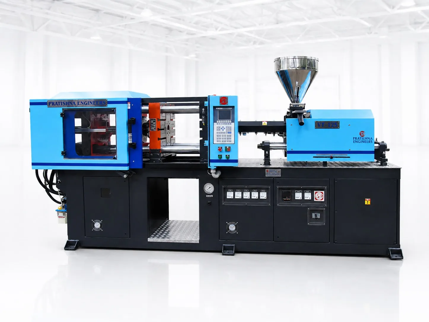
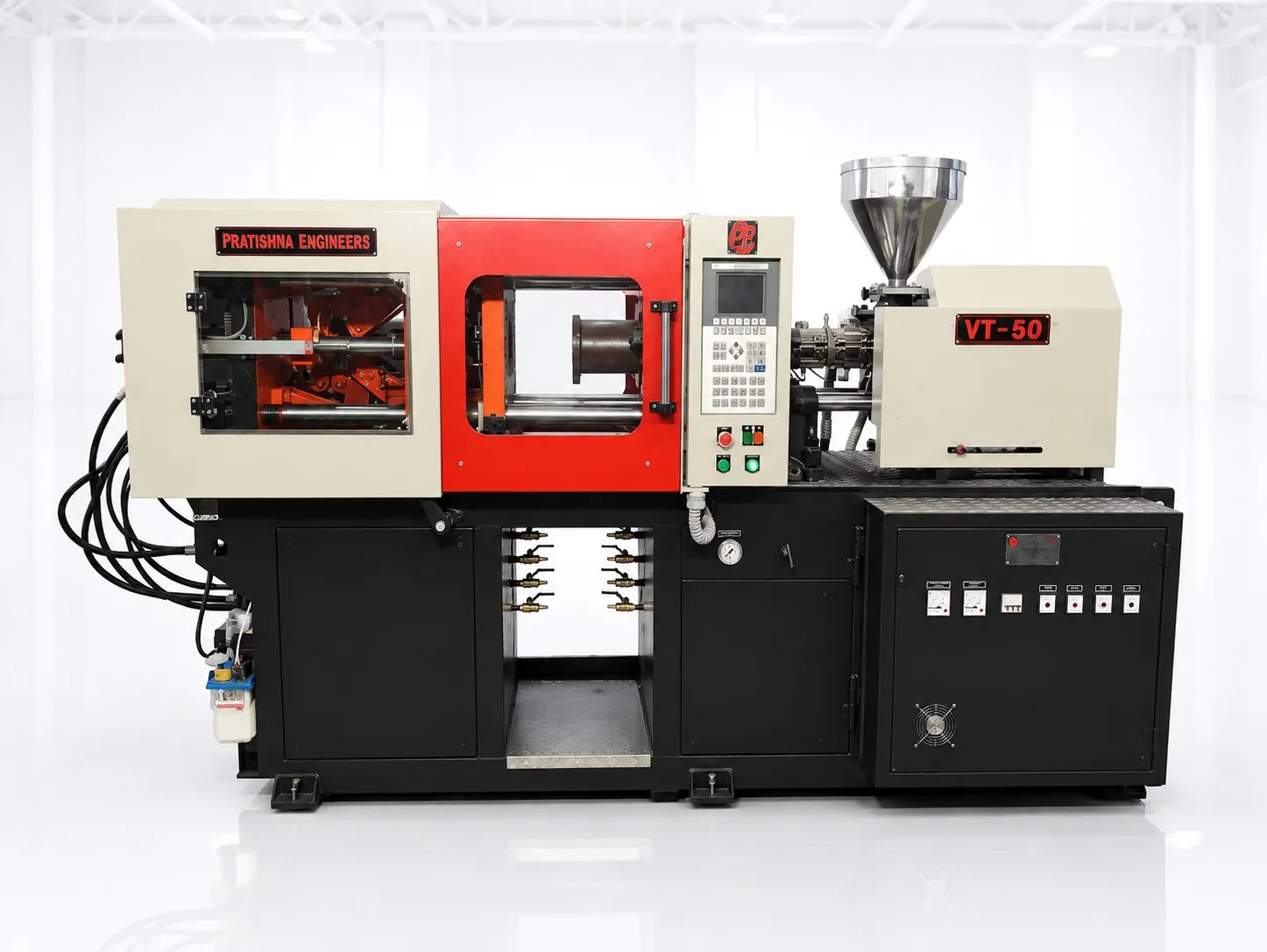
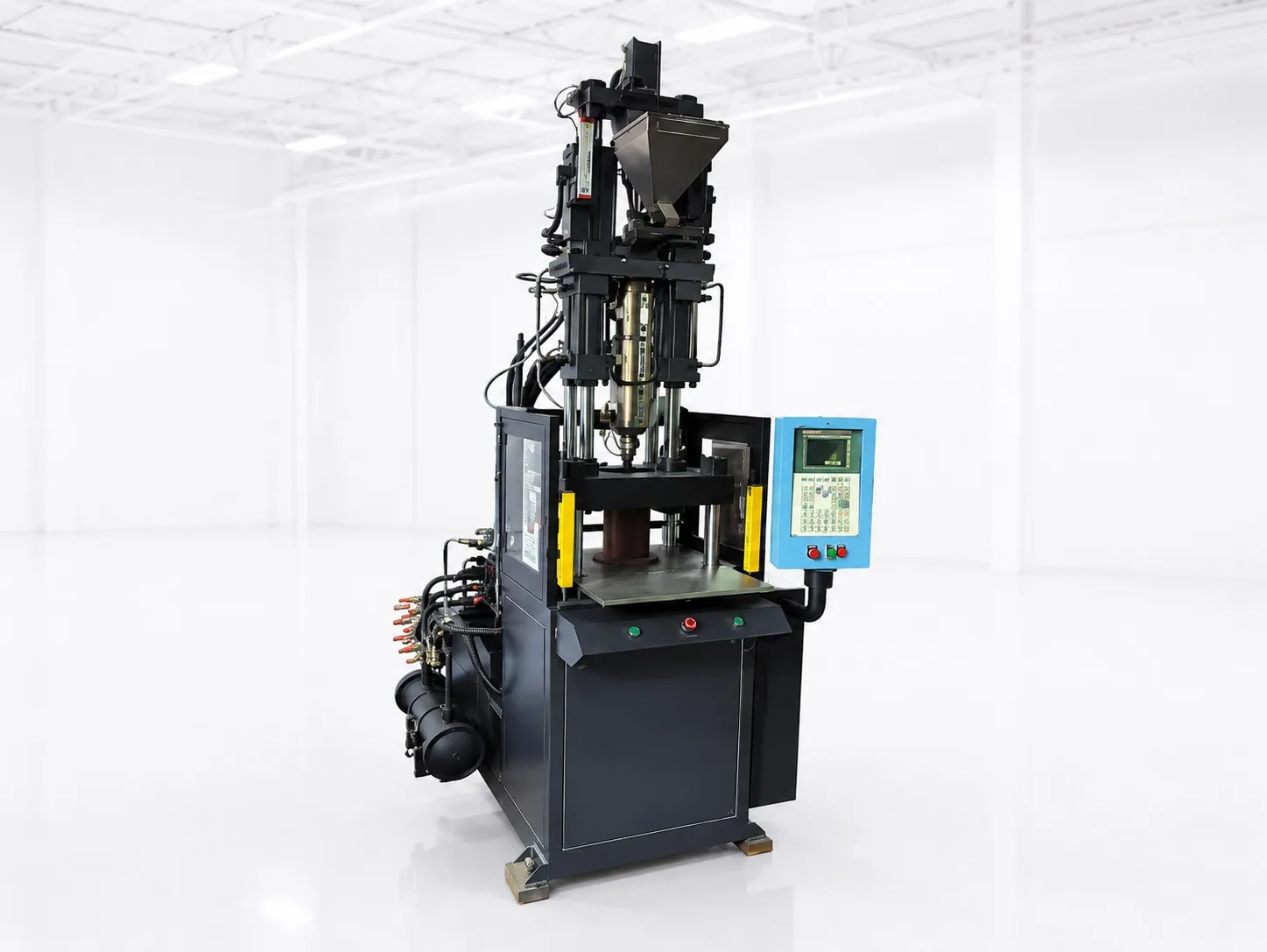
Send the cap drawing or a sample, the neck finish, the resin grade, the target cavity count, the ejection method, the mould's outside size and shut height, and the caps you need per day. With those, clamp, mould fit, shot share and a realistic cycle can be checked together. See the 140 ton container injection moulding machine page.
Frequently Asked Questions About Cap Making Machines
Is it better to add cavities or cut cycle time?
Compare the cost of each. More cavities raise mould price, mould size and shot weight, and can lengthen the cycle slightly. A shorter cycle needs better cooling, a quick dry cycle and steady process control. Work out caps per hour for both options before you decide, as the opening of this article does.
Why do caps from outer cavities differ from inner ones?
Unequal flow length, hot runner temperature or cooling between cavities can cause it. Outer caps may short-fill or shrink differently. Ask the toolmaker for the runner balance and cooling layout, check weight by cavity, and fix the slowest cavity first, because it sets the cycle for all.
Can a cap mould run on chilled water?
Yes, and cooling water can decide a cap's cycle. What matters most is steady flow through every core, a stable supply temperature and clean channels. Scale in cooling lines slows heat removal and can add time to every shot, so include water treatment in the plan for a closure line.
Do unscrewing moulds need a bigger machine?
Not more clamp, but they can need more room. Unscrewing gear trains, motors or racks make the mould longer and wider, which brings shut height and tie-bar space into question. They also add movement to every cycle. Check the complete mould's outside size against the machine before ordering.
How do I estimate caps per day?
Multiply caps per hour by productive hours. Caps per hour is 3,600 divided by the cycle in seconds, times cavities, times the good-shot share. Then allow for mould changes, colour changes, maintenance and start-up scrap, which can take a real share of a day on a busy cap line.
Related Articles
- What Can You Make on a 140 Ton Container Moulding Machine?
- Single-Screw Machines for Closures: Why a 35 mm Screw Suits Light Shots
- 140 Ton vs 180 Ton for Thin-Wall Cups and Small Tubs
Sources & References
- RJG Inc.: How to Determine Injection Molding Cooling Time
- MoldMaking Technology, B. Catoen: Machine Sizing and Specification for Optimal Mold Performance, Part 1 (Aug 2025)
- Packaging Digest, A. Steeman: Short, Shorter, the Shortest (Jan 2014)
- Food Safety and Standards Authority of India: Food Safety and Standards (Packaging) Regulations, 2018, compendium
Technical Disclaimer
Disclaimer: The information provided in this document is for general informational and educational purposes only. It is based on technical references and industry information available at the time of preparation and may be subject to change. It does not constitute engineering, technical, commercial or professional advice, nor does it constitute a quotation, specification, warranty or contractual commitment by Pratishna Engineers.
Actual injection moulding machine and process requirements vary according to the component design, material, mould, production volume, machine configuration and operating conditions. The information, examples, calculations and recommendations provided should be independently evaluated and verified for the specific application before making any equipment, process or production decision. Information obtained from third-party sources remains subject to the accuracy and limitations of those sources.
Limitation of Liability: Pratishna Engineers makes no representation or warranty, express or implied, regarding the completeness, accuracy or suitability of the information for any particular application. To the extent permitted by applicable law, Pratishna Engineers shall not be liable for any loss, damage, cost or consequence arising from reliance on or use of the information contained in this document. Final machine selection, configuration and application suitability should be confirmed with Pratishna Engineers based on complete and accurate project requirements.