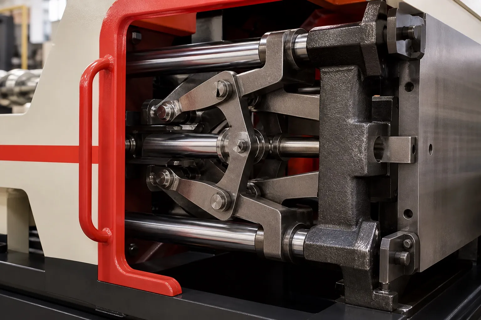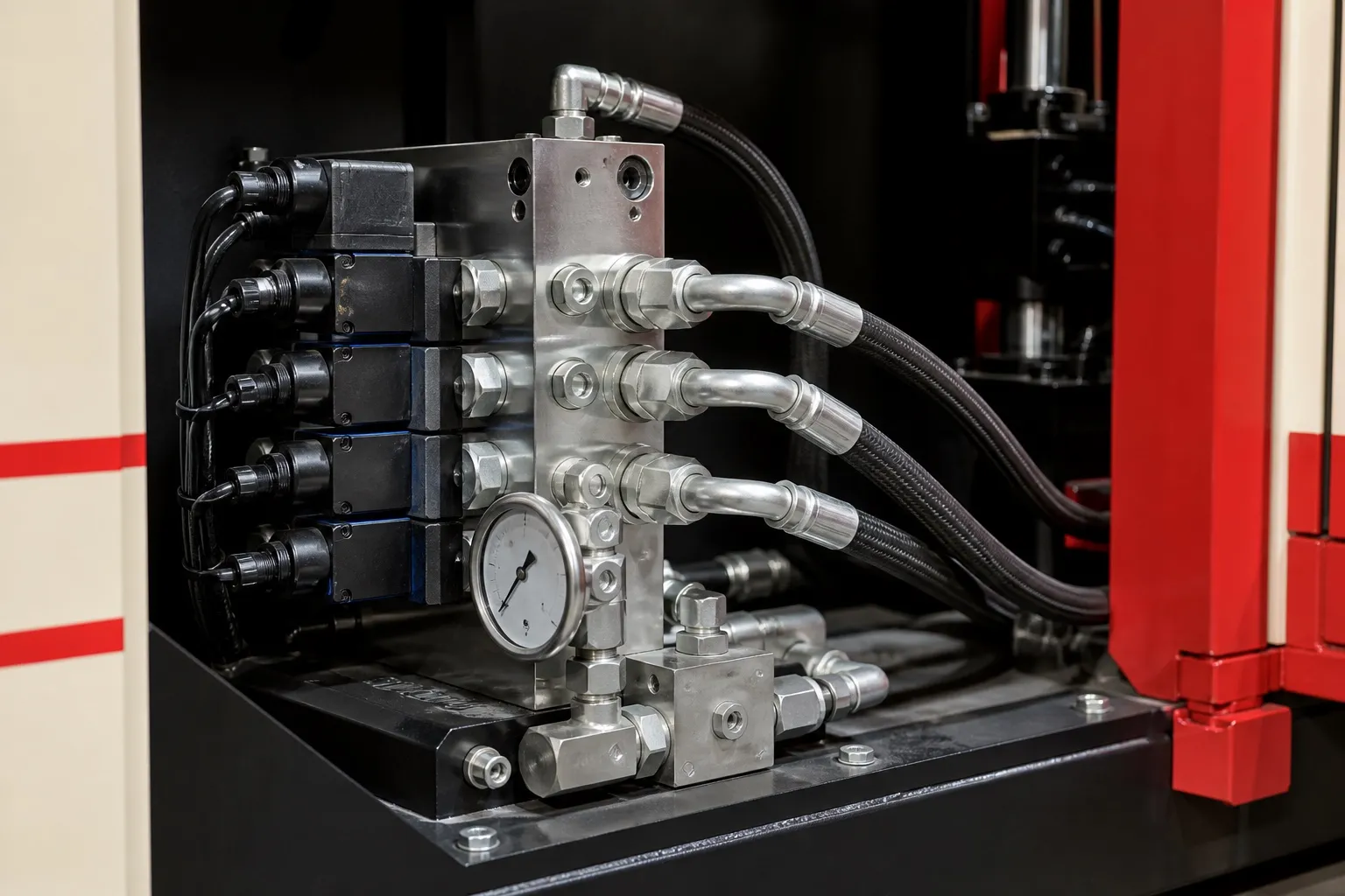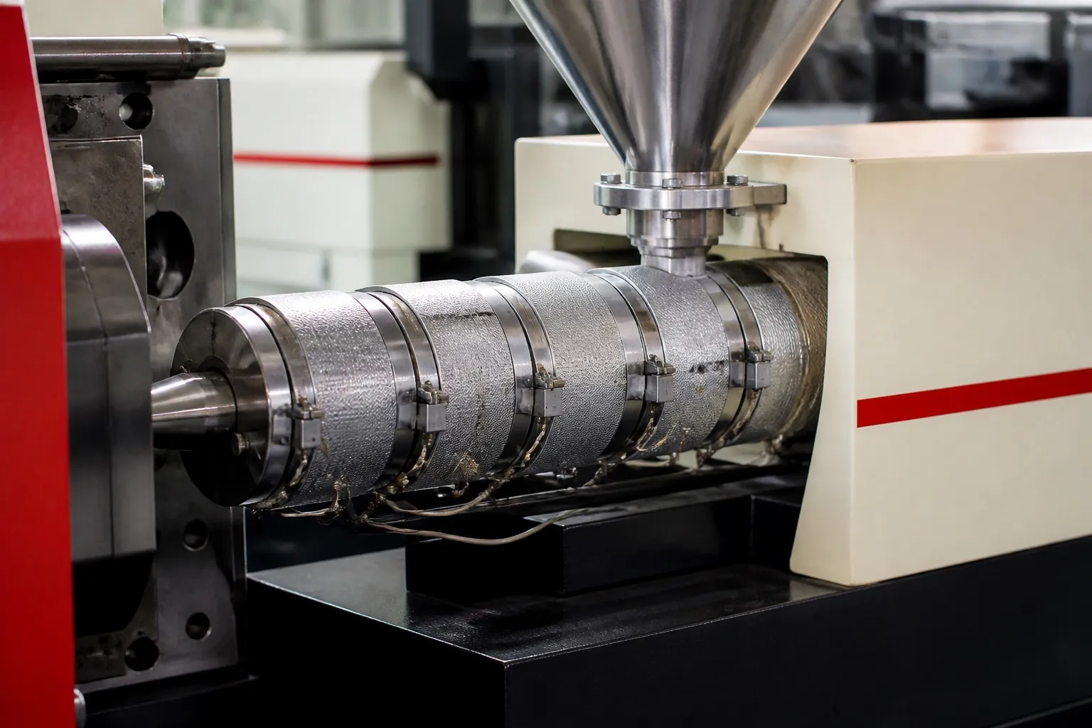






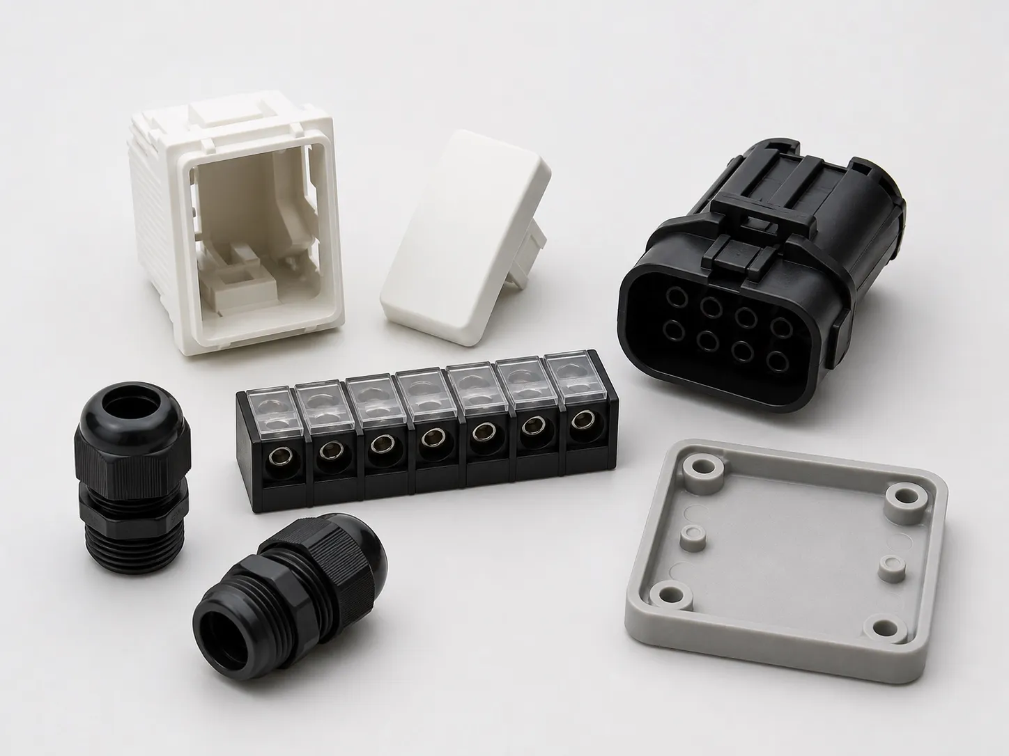

Cable and wire overmoulding forms a plastic part directly on a cable or wire: a plug body, grommet, strain relief, inline connector housing or identification sleeve. On a vertical machine with a horizontal clamp and the injection unit above the mould, the cable lies in the parting line, the two mould halves close on it from either side, and melt enters from the top. The cable tails stay outside the mould, so long leads are easy to handle. Good parts depend on three things: a tight seal where the cable leaves each cavity, a compound that grips the jacket, and a loading routine the operator can repeat every cycle.
This article explains the process, the parts that suit it, the cable exit details that decide scrap, and how to find a sensible cavity count.
Key Takeaways
- The cable crosses the parting line, so every cavity has one or two exits that must seal on a cable whose diameter varies between suppliers and reels.
- Clamp force comes from the projected area of the moulded part and runner, not from cable length, so most cable parts need modest tonnage.
- With manual loading, each added cavity adds loading time, so output rises by less with every extra cavity.
- PVC cords made to IS 694 come under compulsory ISI certification, so treat the incoming cable as a certified product the moulding step must not damage.
How Does Cable and Wire Overmoulding Work on a Horizontal Clamp?
The operator lays the cable in grooves cut into one mould half, with the covered section sitting inside the cavity. The clamp closes the other half against it, the injection unit above fills the cavity through a gate at the parting line, and the part cools onto the jacket.
Because the parting plane stands upright, the cable tails leave the mould at its edges and hang free. A long lead does not need a table to rest on, and the covered section stays where the grooves put it. Both halves can carry cavity detail, and the part leaves the open mould still attached to its cable.
Some parts take one shot: a strain relief or grommet moulded once onto the jacket. Others take two: an inner pre-mould that locks the conductors or pins in place, then an outer shell. Each shot needs its own cavity, either in a second mould or as a second station in the same mould.
Which Cable Parts Suit Parting-Line Injection?
Parts where the cable or wire passes through the mould suit it best: moulded plugs on power cords, inline connector bodies, cable grommets, strain relief boots, sensor lead overmoulds and identification sleeves. Where loose metal inserts sit in pockets and nothing leaves the mould, a vertical clamp usually suits better.
Common cable and wire overmoulded parts and what to watch
| Part | How the cable sits | Main watch-point |
|---|---|---|
| Moulded plug on a power cord | Cord enters one end; pins or a pre-mould sit inside the cavity | Pin position and the seal at the cord entry |
| Strain relief boot | Jacket passes through, usually with a tapered tail | Thick sections and long cooling time |
| Cable grommet | Cable or bundle passes through the centre | Seal lips around the jacket fill last; vent them |
| Inline connector body | Two cables enter from opposite ends | Two exits per cavity, both sealing |
| Sensor lead overmould | Small cable with a sensor or board at the end | Heat and pressure on the component |
| Identification sleeve | Short band around a single wire | Very small shot, so watch residence time |
Plug setup has its own article in this series, and the choice between the two clamp layouts is covered in the clamp article.
What Stops Flash and Crushed Jackets at the Cable Exit?
A shut-off bore sized to the cable you actually receive, not the catalogue nominal, plus injection and hold pressures no higher than the part needs. Too large a bore flashes along the jacket. Too small a bore crushes it, which can damage the insulation underneath.
Cable outer diameter differs between makers and sizes, and can drift between reels, so measure samples from every supplier before the toolmaker finishes the exits. Where one mould must take a range, replaceable exit inserts can be cut for each size band.
Heat matters as much as squeeze. The jacket is itself a thermoplastic, held against hot melt and a warm mould for the whole cycle. The IS 10810 series has separate test methods for deformation of thermoplastic insulation and sheath under pressure at high temperature, and for cracking on overheating, which shows how cable makers treat this risk. Keep the exits cooled and the melt no hotter than the compound needs; the PVC temperature article in this series gives the ranges.
In India, PVC cables to IS 694 are under compulsory certification with the ISI mark through the 2003 Quality Control Order for electrical wires and cables. IS 694:2010 covers cables and cords up to 1,100 V a.c. with conductor temperature limits of 70 °C or 85 °C. The cord reaching your machine is a certified product, and the overmould must not spoil it.
Our view: a cable exit that flashes is a mould problem first. Turning pressure down to hide it trades flash for short shots or sinks elsewhere in the part.
How Many Cavities Can One Operator Load?
On a fixed mould, the cycle is the closed time plus the open time, and each cavity adds laying and checking time. Output still rises with every cavity, but by less each time, so the useful count is where the extra output stops paying for a bigger, costlier mould.
Time the loading on a mock-up before ordering the mould. Cable guides, a stop for the strip length and a clear place to drop finished parts all shorten the open time more than a faster clamp would.
What Should You Send Before Choosing a Machine?
Send the cable specification and measured diameter range, the part drawing with the covered length, the compound, the cavities you plan and your hourly target. With these, clamp, shot and mould size can be checked together. See the horizontal clamp vertical injection moulding machine page.
Frequently Asked Questions About Cable and Wire Overmoulding
Can cables be overmoulded on a horizontal injection moulding machine?
It can be done, with the cable laid across an upright mould face and held by clips or grooves while the clamp closes. The nozzle side of the mould limits where cables can leave, and loading is harder to repeat. A vertical machine puts the cable where the operator's hands naturally reach, which makes it the more practical choice.
Does the overmoulded part bond to the cable jacket?
A PVC part on a PVC jacket can fuse at the interface if the melt is hot enough there. Dissimilar pairs, such as PVC on a polyethylene jacket, may not bond at all. Where bond is weak, design mechanical grip with ribs, a longer covered length or a pre-mould, and confirm it with pull tests on finished samples.
How long should the overmould extend along the cable?
Long enough to pass the pull, torque and flexing tests your product standard sets, and no longer, because extra length in a thick section adds cooling time. Start from the covered length on a similar approved product, mould samples at two lengths and test both before freezing the mould drawing.
Can different cable diameters run in the same mould?
Only within a narrow band. One exit bore that seals on the thickest cable will flash on the thinnest. Replaceable exit inserts let one mould take two or three size bands, with the set changed when the cable changes. Record on the job card which insert set matches which cable size and supplier.
Do cables need any preparation before overmoulding?
Yes. The jacket should be clean and free of oil, talc or release agents that can block bonding. Cut lengths and strip lengths must be consistent, and any crimped terminals must be fully seated. A simple go and no-go gauge at the loading station catches length errors before the cable reaches the mould.
Related Articles
- Moulding Plugs on Power Cords: Machine and Mould Setup
- Horizontal Clamp or Vertical Clamp? Choosing the Right Vertical Machine
- PVC Moulding for Plugs and Grommets: Temperature and Screw Care
Sources & References
- Bureau of Indian Standards, Electrotechnical Department: Compendium of Indian Standards on Power Cables and Accessories (IS 694, IS 10810)
- Bureau of Indian Standards: Scheme I (ISI Mark Scheme): products under compulsory certification
- GEON Performance Solutions: Injection Molding Guide: GEON PVC Molding Formulations (PG0019BC, 2021)
Technical Disclaimer
Disclaimer: The information provided in this document is for general informational and educational purposes only. It is based on technical references and industry information available at the time of preparation and may be subject to change. It does not constitute engineering, technical, commercial or professional advice, nor does it constitute a quotation, specification, warranty or contractual commitment by Pratishna Engineers.
Actual injection moulding machine and process requirements vary according to the component design, material, mould, production volume, machine configuration and operating conditions. The information, examples, calculations and recommendations provided should be independently evaluated and verified for the specific application before making any equipment, process or production decision. Information obtained from third-party sources remains subject to the accuracy and limitations of those sources.
Limitation of Liability: Pratishna Engineers makes no representation or warranty, express or implied, regarding the completeness, accuracy or suitability of the information for any particular application. To the extent permitted by applicable law, Pratishna Engineers shall not be liable for any loss, damage, cost or consequence arising from reliance on or use of the information contained in this document. Final machine selection, configuration and application suitability should be confirmed with Pratishna Engineers based on complete and accurate project requirements.