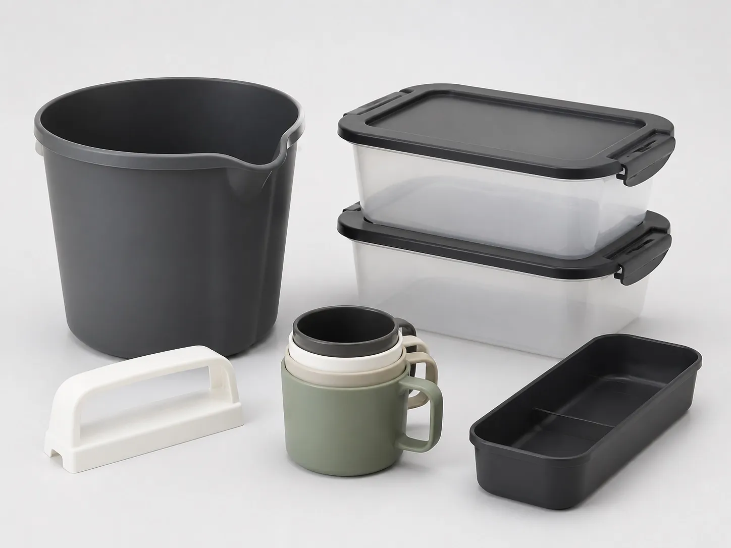
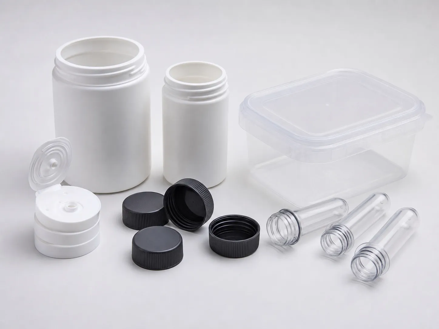

Baskets and trays run well on a 150 t machine when three things are right. The flow length to wall thickness ratio stays below about 150:1, vents let air out wherever the melt arrives last, and walls are even enough that cooling time stays short. On a slotted basket, clamp matters less once the slot area is taken off.
Each of the three has a number you can work out from the drawing before the mould is built. This article gives those numbers and a worked example for a slotted basket.
Key Takeaways
- A flow length to wall thickness ratio below 150:1 carries a low risk of sinks, short shots and dimensional problems.
- Resin suppliers give a vent depth range; one example for PP is 0.013 to 0.051 mm, tuned up from the low end on trial.
- Cooling time scales with wall thickness squared, so a 1.8 mm wall needs about 27% more cooling than a 1.6 mm wall.
- Over-clamping can crush vents, so set clamp from the calculation, not the machine maximum.
How Far Can the Melt Flow in a Basket or Tray Wall?
Divide the longest flow path, from the gate to the farthest point the melt must reach, by the wall thickness. Below about 150:1, the risk of sinks, short shots and dimensional problems is low. Above it, add gates, thicken the wall or choose a higher-flow grade.
The 150:1 guide comes from Jeremy Williams of RJG, writing in Plastics Technology, in a list of factors that raise the clamp a part needs: melt flow, flow length, wall thickness, gate location, gate size and number of gates. A long, thin basket wall raises both the pressure and the clamp.
Baskets are harder than trays of the same size. Every slot splits the melt front, which then has to rejoin beyond it, so the melt travels further and leaves a weld line at each junction. Measure the flow path around the slots, not straight through them.
Trays bring the opposite problem: long open flow across a flat floor. A single centre gate on a large tray sends the melt furthest to the corners, which is where short shots and sinks appear first. Two or more gates, or a hot runner drop near each end, shorten that path.
Flow ratio and relative cooling time for a 258 mm flow path at different walls (calculated; cooling relative to 1.6 mm)
| Wall thickness | Flow ratio (258 mm ÷ wall) | Below 150:1? | Relative cooling time |
|---|---|---|---|
| 1.4 mm | 184:1 | No | 0.77 |
| 1.6 mm | 161:1 | No | 1.00 |
| 1.8 mm | 143:1 | Yes | 1.27 |
| 2.0 mm | 129:1 | Yes | 1.56 |
| 2.5 mm | 103:1 | Yes | 2.44 |
Where and How Deep Should Baskets and Trays Be Vented?
Vent wherever the melt arrives last: the far rim, the corners, the weld lines between slots and the ends of ribs. Start at the low end of the resin supplier's vent depth range and deepen in small steps on trial until a fine flash appears, then back off one step.
Steven Shannon of Estee Lauder sets out this approach in MoldMaking Technology. He gives 0.0005 to 0.002 in, about 0.013 to 0.051 mm, as an example supplier range for PP, and notes that moldmakers usually cut vents at the lowest figure so the mould does not flash on arrival.
His method deepens a spare stack by about 0.005 to 0.008 mm at a time until whisker flash shows, then backs off about 0.005 mm. Secondary vents behind the primary run 0.64 to 0.76 mm deeper, and the primary land is about 1.5 to 2.0 mm. All cavities should then be cut to the same depth.
Poor venting traps air that heats as it is compressed, causing burns, short shots and voids, and can even push the mould halves apart. Shannon also warns that repeated clamping can coin vents shut over time. Williams lists crushed vents among the effects of setting clamp far above what the mould needs.
What Sets the Cycle Time for Baskets and Trays?
Cooling sets most of it, and cooling time depends mostly on wall thickness, which is squared in the cooling equation. Going from a 1.6 mm to a 1.8 mm wall adds about 27% to cooling. The thickest spot, such as a rim or rib junction, sets the whole cycle.
RJG's guide to cooling time reports a trial on a 3.3 mm ABS part in which about 85% of the cycle was cooling. Only about 40% of the heat has to be removed before the part can be ejected, and the guide suggests adding about 20% to the calculated cooling timer as a safety factor.
Resin choice helps here as well. Reliance's Repol B300MN is a high-crystalline PP impact copolymer that its TDS describes as suited to large articles with lower cycle times, thanks to high flow and fast crystallisation. It lists an MFR of 30 g/10 min, a flexural modulus of 1,600 MPa and a notched Izod of 65 J/m.
Our view: on a large tray, keep the wall even and cool both mould halves equally before chasing a faster cycle. A tray that comes out quickly but warps into a saddle is scrap, and uneven cooling between the halves can cause exactly that.
What Should You Check Before Ordering a Basket or Tray Mould?
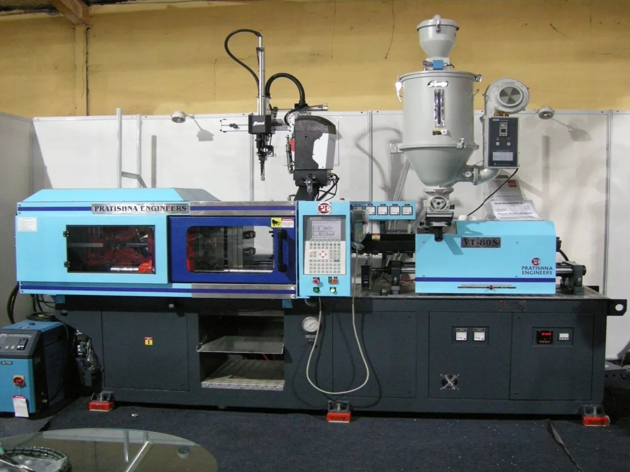
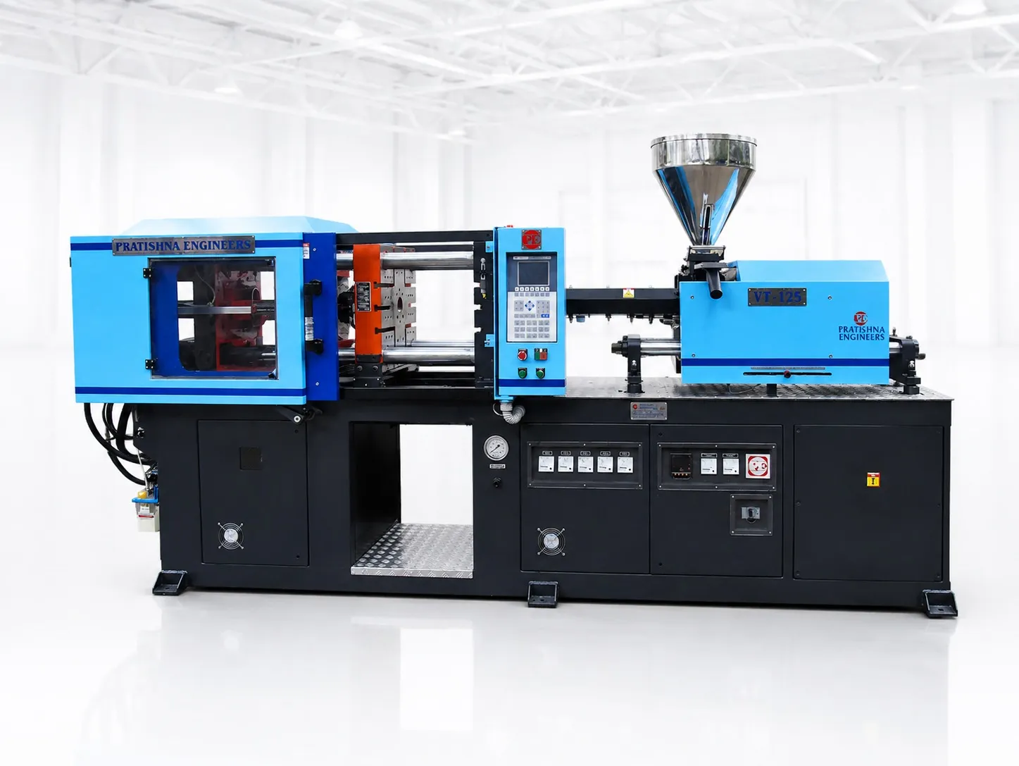
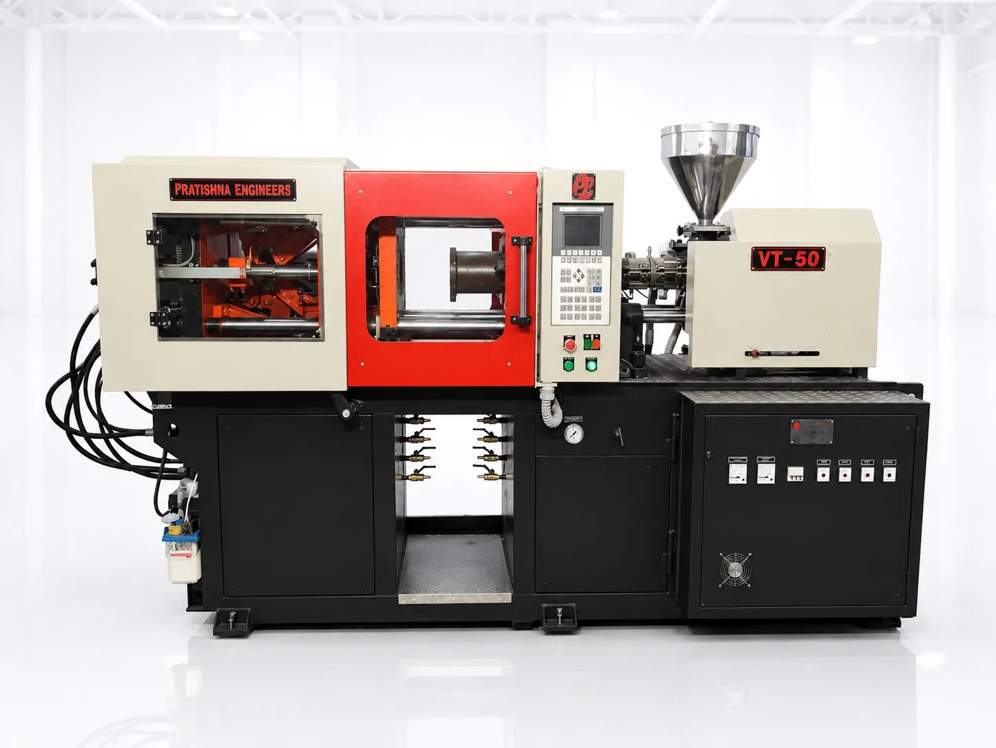
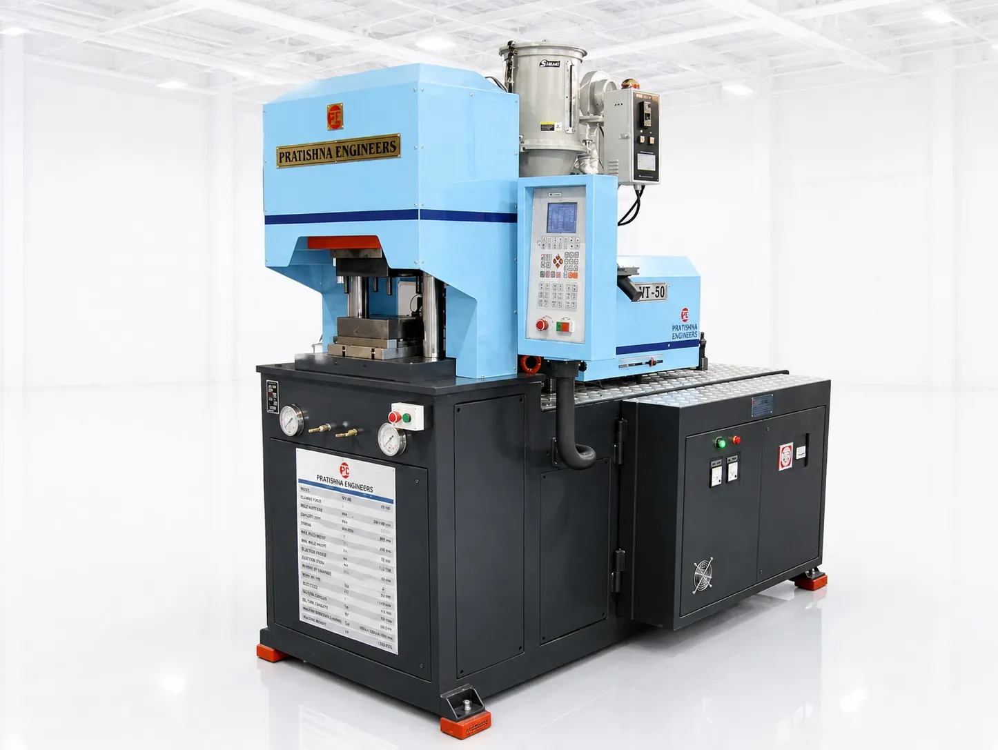
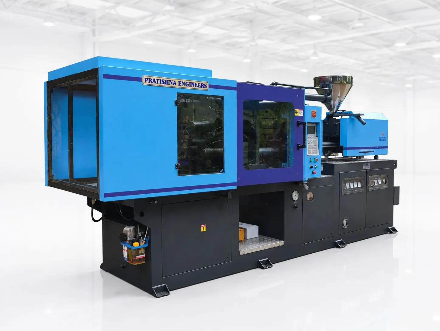
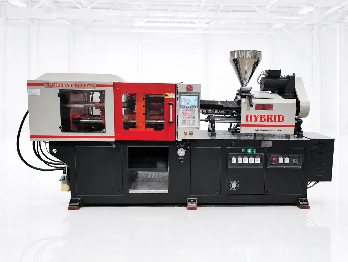
From the drawing, take the longest flow path, the nominal wall, the thickest section and the slot area. Work out the flow ratio, the relative cooling time and the clamp, and ask the toolmaker where the last-to-fill areas will be vented. See the 150 ton horizontal injection moulding machine page.
Frequently Asked Questions About Baskets and Trays
Why do burn marks appear at the corners of a tray?
Air trapped where the melt arrives last is compressed and heats up enough to scorch the plastic. Corners and rim ends are typical spots. A vent at that point, cut to the right depth, can clear it. Slowing injection near the end of fill can help while the vent is being added.
How do I stop weld lines around basket slots from cracking?
Make the melt fronts meet hot and under pressure. Gate so the fronts meet as early as possible, keep melt and mould temperature within the resin's range, and vent each weld line so trapped air does not hold the fronts apart. An impact copolymer also tolerates weld lines better in service.
Will colder mould water shorten the cycle on a thick tray?
Only up to a point. Cooling is limited by how fast heat moves through the plastic wall, and that depends on thickness more than water temperature. Colder water can also cause condensation and uneven shrinkage. Better flow through the mould channels, and a thinner, even wall, can give more.
Why do large trays warp after ejection?
Uneven shrinkage pulls the tray out of flat. Causes include one mould half running hotter than the other, walls of different thickness, and flow that orients the plastic more in one direction. Balanced cooling, even walls and a gate position that gives uniform flow are the main fixes.
Can vents be added after the mould is built?
Yes. Vents are cut into the parting line or around ejector pins and inserts, so a toolroom can add or deepen them on a finished mould. Go in small steps and test after each one, because a vent cut too deep makes flash, and a too-deep vent is harder to correct.
Related Articles
- What Can You Make on a 150 Ton Household Moulding Machine?
- Casseroles and Thermoware Shells on a 150 Ton Machine
- 45 mm or 50 mm Screw? Choosing for Household Articles
Sources & References
- Plastics Technology, J. Williams (RJG): Clamp Tonnage: More Is Better...Right?
- MoldMaking Technology, S. Shannon (The Estee Lauder Companies): How to Determine the Proper Vent Depth
- RJG Inc.: How to Determine Injection Molding Cooling Time
- Reliance Industries: Repol B300MN Technical Data Sheet
Technical Disclaimer
Disclaimer: The information provided in this document is for general informational and educational purposes only. It is based on technical references and industry information available at the time of preparation and may be subject to change. It does not constitute engineering, technical, commercial or professional advice, nor does it constitute a quotation, specification, warranty or contractual commitment by Pratishna Engineers.
Actual injection moulding machine and process requirements vary according to the component design, material, mould, production volume, machine configuration and operating conditions. The information, examples, calculations and recommendations provided should be independently evaluated and verified for the specific application before making any equipment, process or production decision. Information obtained from third-party sources remains subject to the accuracy and limitations of those sources.
Limitation of Liability: Pratishna Engineers makes no representation or warranty, express or implied, regarding the completeness, accuracy or suitability of the information for any particular application. To the extent permitted by applicable law, Pratishna Engineers shall not be liable for any loss, damage, cost or consequence arising from reliance on or use of the information contained in this document. Final machine selection, configuration and application suitability should be confirmed with Pratishna Engineers based on complete and accurate project requirements.